Multifunction overview, 10 dc power connector internal, Dc power connector internal – Kontron KTT30-mITX User Manual
Page 29: Ktt30/mitx users guide multifunction overview
KTD-N0857-A
Page 26
Pin Connectors
KTT30/mITX Users Guide
Multifunction Overview
The following table informs about the dependencies.
I/O Pin
NVIDIA
®
Label
Second Function
GPIO0
Q.01
Keyboard column 1
GPIO1
Q.02
Keyboard column 2
GPIO2
Q.03
Keyboard column 3
GPIO3
Q.04
Keyboard column 4
GPIO4
Q.05
Keyboard column 5
GPIO5
Q.06
Keyboard column 6
GPIO6
Q.07
Keyboard column 7
GPIO7
R.00
Keyboard row 0
GPIO8
R.01
Keyboard row 1
GPIO9
R.02
Keyboard row 2
GPIO10
R.03
Keyboard row 3
GPIO11
R.04
Keyboard row 4
GPIO12
R.05
Keyboard row 5
GPIO13
S.01
Keyboard row 9
GPIO14
S.02
Keyboard row 10
GPIO15
S.03
Keyboard row 11
GPIO16
S.04
Keyboard row 12
GPIO17
S.05
Keyboard row 13
8.10
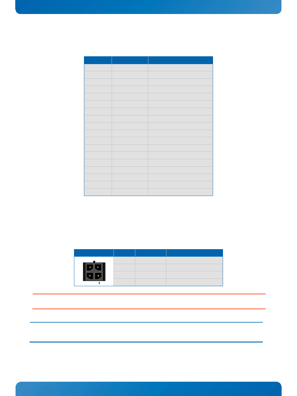
DC Power Connector Internal
The KTT30/mITX board has a power input voltage range from +4.5V to +5.5V. The power supply is connected
via the connector J17 (4 pin Micro-Fit) or alternatively the external Power connector J2 (3 pins, DC power
jacket 2.1mm). Notice that the +5V power lines on J2 and on J17 are connected on the board.
Header
Pin
Signal
Description
1
VCC5
1)
Power supply +5V
2
GND
Ground
3
GND
Ground
4
VCC5
1)
Power supply +5V
Warning: Do not overload the onboard system voltage +3.3V resp. 1.8V (SD
TM
card socket, digital I/O connector). The maximum
current should not exceed 250mA.
Note:
1)
To protect the external power lines of peripheral devices make sure that
- the wires have the right diameter to withstand the maximum available current.
- to enclosure of the peripheral device fulfills the fire-protecting conditions of IEC/EN 60950.