Cp-rio3-05 functional description – Kontron CP-RIO3-05 User Manual
Page 29
CP-RIO3-05
Functional Description
ID 1044-0711, Rev. 1.0
Page 2 - 7
P R E L I M I N A R Y
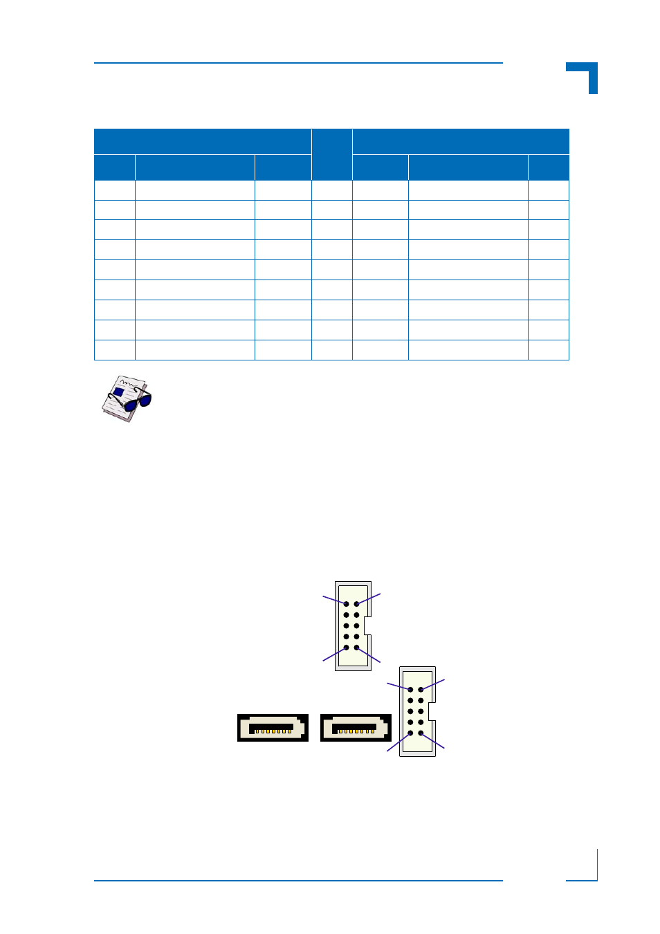
The following figure and tables provide pinout information for the onboard COM connectors J2
and J3.
Figure 2-5: Onboard Serial Port Connectors J2 (COM1) and J3 (COM2)
Table 2-5: D-Sub COM Connector J3a (COM2) Pinout
RS-232
PIN
RS-422
I/O
DESCRIPTION
SIGNAL
SIGNAL
DESCRIPTION
I/O
--
Not connected
NC
1
NC
Not connected
--
I
Receive data
RXD
2
RXD+
Receive data +
I
O
Transmit data
TXD
3
TXD-
Transmit data -
O
--
Not connected
NC
4
NC
Not connected
--
--
Signal ground
GND
5
GND
Signal ground
--
--
Not connected
NC
6
NC
Not connected
--
O
Request to send
RTS
7
TXD+
Transmit data +
O
I
Clear to send
CTS
8
RXD-
Receive data -
I
--
Not connected
NC
9
NC
Not connected
--
Note ...
The RS-232 signals DCD, DTR, DSR, and RI are not supported on the J3
connector.
J3
COM2
J2
COM1
1
9
10
2
1
9
10
2
- CP3003-SA uEFI BIOS (72 pages)
- CP3003-SA (36 pages)
- CP3002 (38 pages)
- CP3002-RC uEFI (64 pages)
- CP3002-RC (30 pages)
- CP342 (52 pages)
- CP930 (46 pages)
- CP932 (52 pages)
- CP346 (72 pages)
- CP384 (66 pages)
- CP383 (74 pages)
- CP382 (58 pages)
- CP381 (60 pages)
- CP372 (64 pages)
- CP371 (60 pages)
- CP-RIO3-04S (38 pages)
- CP390 (36 pages)
- CPS3410 (9 pages)
- CPS3402 (9 pages)
- CPS3105 (9 pages)
- CPS3101 (9 pages)
- CPS3003-SA (19 pages)
- PB-SIO4 (34 pages)
- PB-SIO4A (34 pages)
- PB-DOUT8 (34 pages)
- VMOD-2 (82 pages)
- VSBC-32 (110 pages)
- VM42 (62 pages)
- Bootstrap Loader (24 pages)
- VMP1 with Netbootloader (120 pages)
- VMP1 (106 pages)
- NetBootLoader (86 pages)
- VMP2 (142 pages)
- VMP3 (154 pages)
- CP-RIO6-923 (32 pages)
- CP-RIO6-923-F (32 pages)
- CP-RIO6-001 (28 pages)
- CP-RIO6-001-HD-VGA (46 pages)
- CP-RIO6-M (20 pages)
- CP-RIO6-B (28 pages)
- CP6925 (42 pages)
- CP6002 uEFI BIOS (76 pages)
- CP6002 IPMI (40 pages)
- CP6002 (42 pages)