ETS-Lindgren 2187 Turntable User Manual
Page 23
Assembly and Installation
|
23
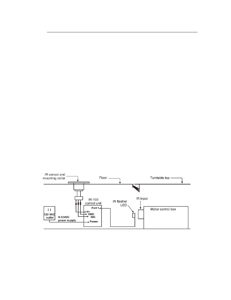
IR Repeater Installation
I
NSTALLATION
A
SSEMBLY
C
OMPONENTS
• Infrared
sensor
• Mounting
collar
•
IR-100 control unit
•
IR flasher LED
• 9–12VDC
power
supply
• Connection
cable
•
Flathead mounting screws
R
EQUIRED
T
OOLS FOR
I
NSTALLATION
• Electric
drill
•
1-in hole saw to create a
•
1/16-in drill bit
•
Small flat blade screwdriver
•
Phillips #2 bit driver
• Adhesive
tape
I
NSTALLATION
S
TEPS
1. Choose a location for the IR infrared sensor that is away from traffic.
2. Using a 1-in hole saw, cut an opening in the floor for the IR sensor.
3. Connect the V+, GND, and SIG wires to the IR sensor as shown in the
diagram, and feed the cable through the hole.
See also other documents in the category ETS-Lindgren Equipment:
- SMART 200 Reverb Chambers (45 pages)
- 6402 Helmholtz Coil (24 pages)
- 3625-2 LISN (15 pages)
- 3701 Line Probe (15 pages)
- 3725-2M LISN (19 pages)
- 3810-2 LISN (25 pages)
- 3816-2 LISN (21 pages)
- 3850-2 LISN (19 pages)
- 4825-2 LISN (25 pages)
- 1052 Antenna Tower Positioner (23 pages)
- 2005 Single Axis Positioner (32 pages)
- 2090 Controller (178 pages)
- 2110 Multi-Axis Positioning Systems (MAPS) (48 pages)
- 2115 Multi-Axis Positioning Systems (MAPS) (48 pages)
- 2165 Turntable (46 pages)
- 2171B Boresight Antenna Tower (64 pages)
- 2175 Antenna Tower (41 pages)
- 2181 Turntable (44 pages)
- 2188 Turntable (39 pages)
- 7-TR Tripod Positioner (49 pages)
- 7000-001 EMCenter Modular RF Platform (41 pages)
- 7405 E & H Near Field Probe Set (51 pages)
- 91197-1 Current Probe (57 pages)
- 95236-1 Current Probe (27 pages)
- HI-1501 Microwave Oven Survey Meter (28 pages)
- HI-1600 Microwave Oven Survey Meter (26 pages)
- HI-1710A Microwave Oven Survey Meter (57 pages)
- HI-1801 Microwave Oven Survey Meter (24 pages)
- HI-2200 RF Survey Meter (53 pages)
- HI-2602 Interlock Monitor (22 pages)
- HI-2790B Calibration Comparison System (44 pages)
- HI-3603 VLF Survey Meter (55 pages)
- HI-3604 ELF Survey Meter (44 pages)
- HI-3624(A) Survey Meter (22 pages)
- HI-3627 ELF Magnetic Field Meter (36 pages)
- HI-3637 VLF Magnetic Field Meter (48 pages)
- HI-3638 ELV/VLF Electric Field Meter (41 pages)
- HI-3702 Induced Current Meter (34 pages)
- HI-3804 RF Industrial Compliance Meter (25 pages)
- HI-4416 Numeric EMF Readout Unit (38 pages)
- HI-4433-CH Magnetic Field Probe (42 pages)
- HI-6005 Electric Field Probe (152 pages)
- HI-6100 Field Monitor (71 pages)
- HI-6113 Laser Data Interface and Probe Measurement System (49 pages)