Elecraft AF1 Audio Filter User Manual
Page 5
5
Install the stereo jacks using the same procedure you used for the 12VDC connector above:
__ J1
__ J3
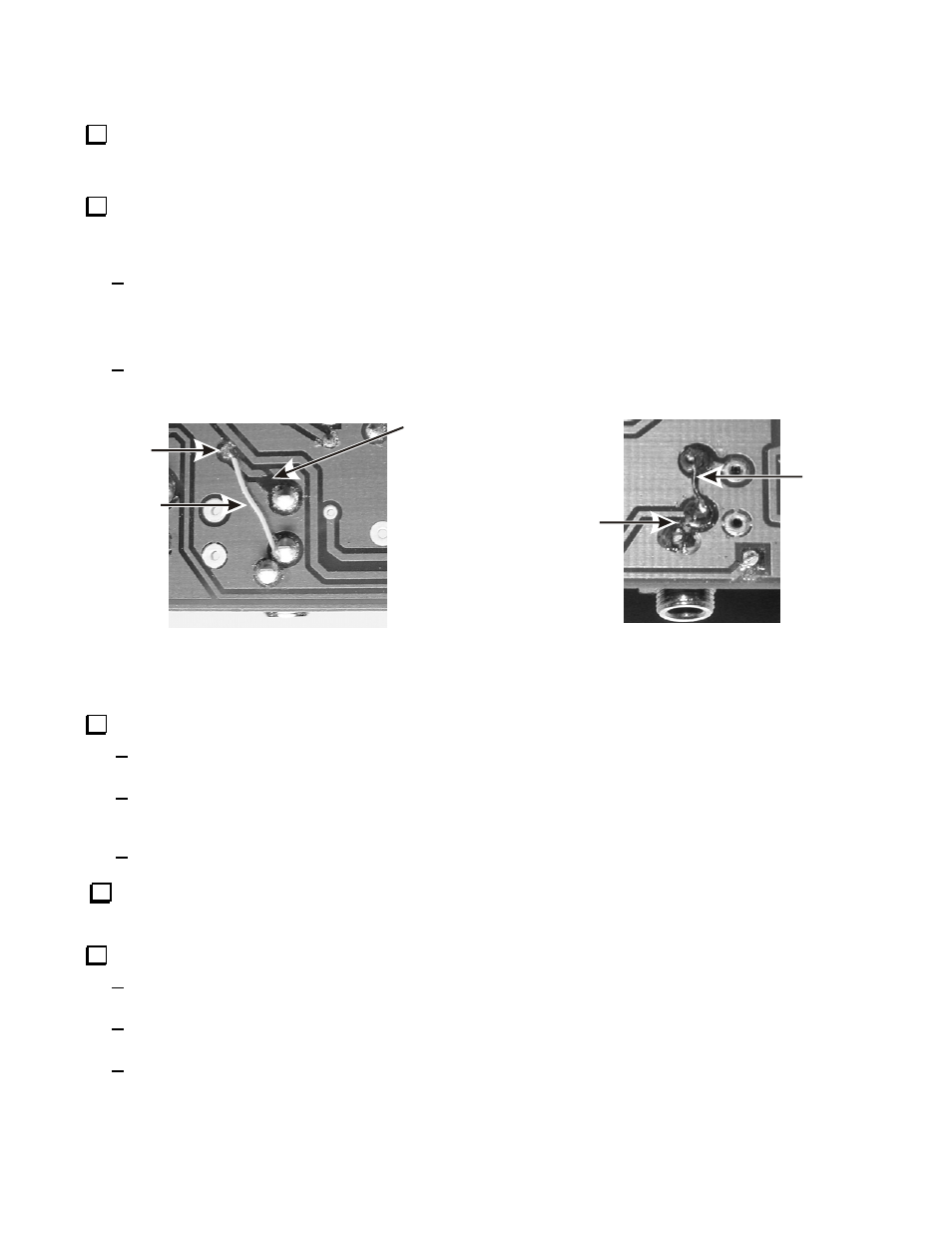
If the circuit board in your kit is Revision A (shown in the lower left corner on the top of the board), make the following
changes so it will work properly with a monaural plug at the input and a stereo plug at the output. Skip this step if your circuit
board is a later revision.
At the pins of J1 (AF IN) on the bottom of the board, use a sharp knife to cut and remove the segment of the trace
shown below. Use the green insulated wire to make a jumper to reach between the pin on J1 shown and the small
hole at the circuit via where the trace passes through to the top of the board. This change isolates the ring connection
so a monaural plug at J1 it won’t short the audio to ground.
At the pins of J3 (AF OUT) on the bottom of the board, install a jumper between the pins shown below. Use a short
section of the green insulated wire or a discarded component lead. Take care to ensure the middle connection of J3 is
not shorted to ground. This ties tip and ring together so audio is present on both at the output.
JUMPER
CIRCUIT
VIA
J1 - AF IN
J2 - AF OUT
CUT TRACE HERE
JUMPER
BE CAREFUL
NOT TO CREATE
A SHORT TO
GROUND HERE
Figure 3. Rev. A Board Modifications.
Install 6-pin dual potentiometer R10 as follows:
Position R10 on the board. Be sure all six pins pass through their respective solder pads, then press down on the
body of the potentiometer, if necessary, to snap it in place. Do not push on the shaft.
Solder only one pin, then inspect the potentiometer to be sure it is sitting flat against the board. Look at it from two
directions to be sure the shaft is perpendicular to the board. If necessary, reheat the soldered pin and reposition the
R10.
Solder all six signal pins and the two side clips to the board.
Install potentiometers R5 and R15 using the same procedure you used for R10:
__ R5 (50KB)
__ R15 (10KD)
Install rotary switch SW1 as follows:
Position SW1 inside its outline on the board. Note that the pins will fit through the solder pads when the switch is
oriented one way.
Solder one pin and inspect the switch to be sure it is perpendicular to the board, just as you did for the
potentiometers.
Solder all the pins.