Elecraft AF1 Audio Filter User Manual
Page 4
4
Install the capacitors listed below just as you did with the resistors in the previous step:
__ C5, .0022µF (222)
__ C4, .01µF (103)
__ C6, .1µF (104)
__ C12, .047µF (473) See note.
__ C8, .01µF (103)
__ C7, .01µF (103)
__ C13, .01µF (103)
__ C9, .01µF (103)
Note: The + symbol next to outline for C12 refers to electrolytic capacitor C11
that you’ll install later. C12 may be installed oriented either way, just like the
other capacitors in this group.
Locate LED D3. Note that one lead is slightly longer than the other. Insert the long lead in the lower, round solder pad
in the space for D3 on the left edge of the board. Position the LED as close to the board as it will fit. Solder and trim the leads
flush with the bottom of the board.
Locate diodes D1 and D2 (1N4007). Note the silver band at one end of the diode body. Install the diodes with the silver
stripe aligned with the stripe on the silk screened outline on the board.
__ D2, 1N4007 (near upper left corner)
__ D1, 1N4007 (near upper right corner)
Inspect the leads of one of the electrolytic capacitors. Note that there is a stripe with a – on the body to identify the
negative lead. The negative lead must be inserted in the round solder pad on the board. The positive lead must be inserted
in the square solder pad. There is a + symbol near that pad. The positive lead is slightly longer on most capacitors. Install the
electrolytic capacitors as follows:
__ C2, 470µF
__ C3, 470µF
__ C1, 1µF
__ C11, 470µF
__ C10, 1µF
Bend the clipped resistor lead you saved earlier into a “U” that fits into the solder pads at each end of the GND test point
near C9. Solder the lead into the pads with the loop high enough above the board to easily clip a test probe lead onto it.
Install U1 (LM348) as follows:
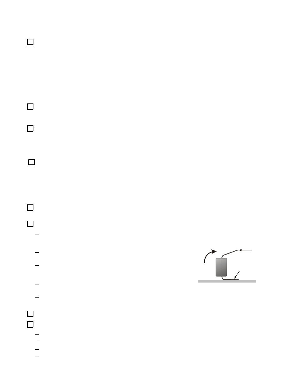
Place U1 on the board where shown by the outline near the bottom center. If the pins are spread too wide to fit, place
U1 on its side on a solid, flat surface and rock it gently to bend all the pins inward slightly as shown in Figure 2. Do
the same on both sides until it fits into the solder pads on the board.
Align the end of U1 that has a notch or dimple molded in the case
with the notch on the silk screened outline.
Hold U1 in place, wet the tip of your soldering iron with solder and
touch one of the corner pins on the bottom of the board to tack-solder
it in place.
Make sure U1 is correctly positioned and flat against the board, then
solder the remaining pins.
Reheat the tack-soldered pin as needed to ensure it is properly
soldered.
Install U2 (LM386) using the same procedure you used for U1.
Install the 12VDC power connector, J2, as follows:
Position the connector over the J2 outline on the board.
Tack-solder one pin to hold it in place.
Check the position of the connector. If necessary reheat the soldered pin to adjust it.
Solder the remaining two terminals, then finish soldering the terminal you tacked in place.
FLARED
STRAIGHT
PRESS AND
ROCK TO
STRAIGHTEN
Figure 2. Straightening I.C. Pins.