Elecraft XV 432 Assembly Installation Instruction User Manual
Page 2
Elecraft XV432 High Accuracy Crystal Option Installation Instructions
Page 2 of 2
Install the new L19 (yellow form). Be sure it is down against
the board and solder it in place.
Replace the crystal oven (if used).
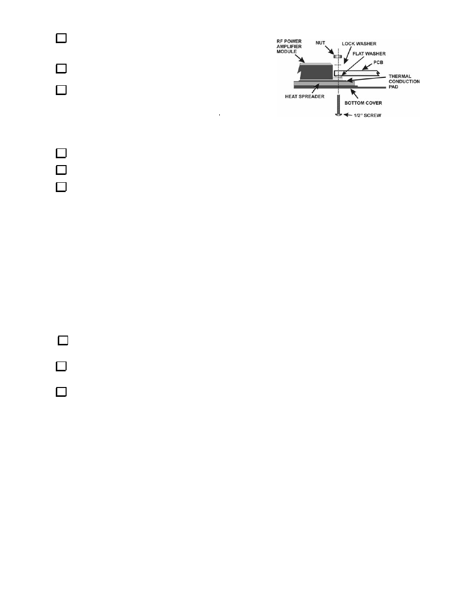
Replace the bottom cover on your XV432. Be sure to replace
the hardware around the RF power amplifier module as shown in
Figure 2, especially the flat washer between the pc board and
module, otherwise your power amplifier may overheat and fail.
Alignment
Preset the slug in L19 so it is flush with the top of the form.
Preset the slug in L4 so it is two turns down into the form from the top.
Choose and set up your equipment to measure the local oscillator frequency using one of the following:
a) Connect a frequency counter to either end of molded inductor (L3) near T1 on the RF board to measure the local
oscillator frequency directly. This method connects your counter to a circuit containing direct current. If your
counter isn’t protected against d-c levels (or you aren’t sure) connect the counter through a capacitor. Any value
from 100 pF to 0.01 µF is suitable.
b) Connect a dummy load to your transverter output and connect a frequency counter to sample the RF output from the
transverter. Do NOT connect your counter directly to the antenna output without a suitable attenuator to
protect the counter input. If you do not have a suitable attenuator, connect an insulated wire to the counter input
and position the wire near antenna relay K1 on the RF PCB. You may need to experiment with the position of the
wire to pick up enough RF to operate the counter. Do not wrap the wire around L10 or L11. That would detune the
output filter and could damage the RF power module. Be sure your transceiver SPLIT and RIT functions are off and,
if using a K2 or K3, be sure the XV offset (in the MENU) is set to zero.
c) Set up an external signal source at 432.000 MHz that you will receive to measure the frequency, either tuning your
transceiver for zero beat or by centering the signal in the i.f. bandpass. Be sure your transceiver SPLIT and RIT
functions are off and, if using a K2 or K3, be sure the XV offset (in the MENU) is set to zero.
Connect a DMM to measure the voltage at TP1 (2 to 3.5 vdc). This voltage will indicate whether the local oscillator is
starting reliably and with the proper output level.
Turn on the equipment, including the XV432 and (if used) the associated transceiver and allow it to warm up at least 10
minutes.
Adjust L4 and L19 for a local oscillator frequency of exactly 404 MHz if measuring the L.O. directly, or for the correct
transmitted or received signal frequency if using methods b) or c) to measure the local oscillator frequency indirectly. After
adjusting, turn power to the transverter off and on while monitoring the DMM to ensure it starts reliably and the voltage at
TP1 is between 2 and 3.5 vdc. Start your adjustments with L4 and, if its range is not adequate to provide the correct
frequency and reliable oscillator startup, adjust L19. Both coils raise the local oscillator frequency as the core is extracted and
lower the frequency as they are moved deeper into the coils. If the voltage at TP1 is outside the range of 2 and 3.5 vdc, adjust
L4 and compensate with L19 to return to the correct frequency.
That completes the installation of your high-accuracy local oscillator crystal.
Figure 2. RF Module Mounting Hardware.