Elecraft KNB2 Manual Errata User Manual
Page 2
Page 2 of 2
4. Page 3, third step: change the last sentence to read:
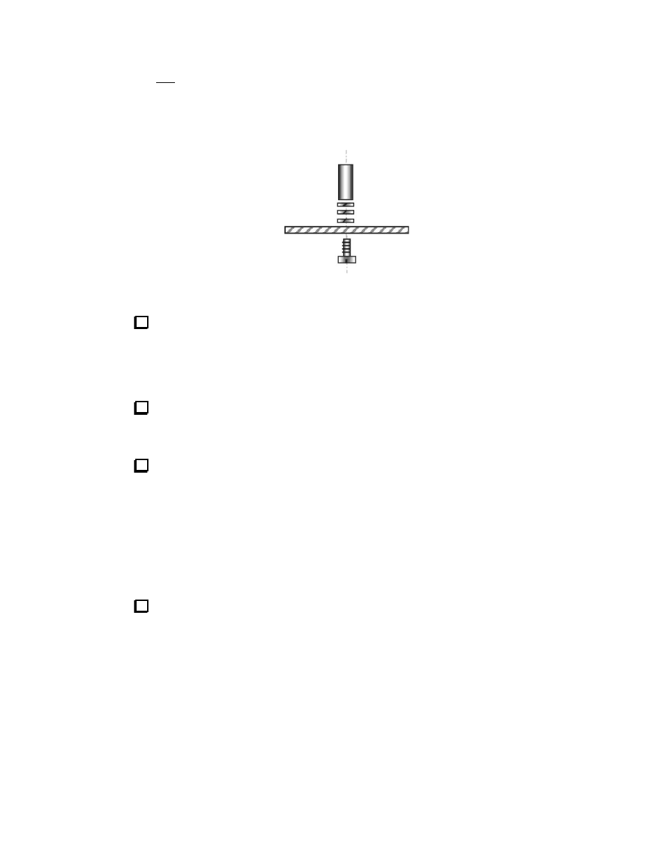
Use two THREE split lock washers between the standoff and the top of the RF board in
order to position the module at the correct height. Do NOT place a lock washer between the
screw head and the bottom of the K2
’s RF board.
Replace the illustration after the step with the following:
5. Page 3, fourth, fifth and sixth steps (the remaining steps after the figure): Replace them
with the following:
Cut a strip of thin card stock (such as a business card) that covers Q22 on the
K2 RF board and which extends out toward the rear about 1” Place it on top of
the Q22. It will be used to determine whether the resistors on the bottom of the
KNB2 board touch Q22 or its heat sink. Several layers of common paper may be
used instead of the card stock.
Plug the noise blanker module into J12 (above Q22), being careful to line up
all of the pins of P1 with J12. Secure the module to the standoff provided using a
1/4" (6 mm) screw and one split lock washer.
Remove the strip of thin card stock. It should slide out freely with no
resistance. If it is pinched between the noise blanker module and Q22, remove
the screw and lift the noise blanker module off to correct the spacing. Likely
causes of the problem are that the resistors on the bottom of the noise blanker
module are not mounted against the pc board, the heat sink on Q22 is not
mounted all the way down against the flange on the transistor, Q22 itself is not
mounted flat against the K2 RF board, or that you failed to place three lock
washers between the spacer and the pc board as shown above. Correct the
problem and replace the noise blanker module before proceeding.
Reinstall the bottom cover (6 screws).