Elecraft KNB2 Manual Errata User Manual
Elecraft Accessories communication
Page 1 of 2
E
l e c r a f t K N B 2 M A N U A L E R R A T A
R e v . D - 3 , F e b r u a r y 2 4 , 2 0 1 4
T H E F O L L O W I N G C H A N G E S T O T H E M A N U A L M U S T B E M A D E
B E F O R E P R O C E D I N G O R T H E K N B 2 W I L L N O T F U N C T I O N
C O R R E C T L Y
1. Page 2, Parts Inventory, U1 (third item from bottom): Change the description to read “RF Amplifier, SMD
on daughter board, SMT1A P/N E120013, with two 4-pin headers, P/N E620146”.
2. Page 4, second step: Delete reference to “U1”. (Only U3 will be installed at this time; U1 will be installed
later.)
3. Page 5, third step: Insert a note between the third and fourth steps to perform the following steps at this point
in the procedure:
Note: An RoHS compliant surface mount version of the MC1350 integrated circuit is
used at U1. This device is furnished pre-installed on a tiny printed circuit board that
mounts in the space originally provided for the 8-pin dual in-line (DIP) version of the
part.
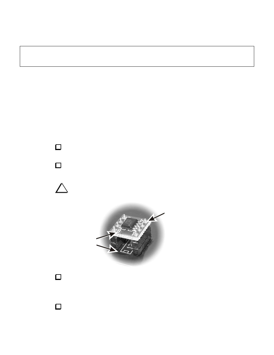
Locate the SMT1A board and the two four-pin headers provided. Insert the
pins of the headers into the solder pads in the SMT1A board as shown below.
Position the SMT1A board and headers into the solder pads for MC1350 U1
as shown. Be sure pins 1 and 8 on the SMT1A board are at the end with the notch
shown in the outline on the KNB2 board.
i
When soldering the header pins, do not apply heat for more than two or
three seconds at a time to avoid melting the plastic header.
Pins 1 and 8
must be at
end above
the notch
outline on
the board
Solder
(8 places
on top)
Solder the pins on the bottom of the board. Solder a pin at opposite corners
first, then make sure the headers are resting against the board. If necessary re-
heat the pins while pressing the assembly against the KNB2 board. When the
assembly is in position, solder all 8 pins.
Continue with the assembly procedure at step four on page 5 of the KNB2
manual.