Elecraft KBT1 Manual User Manual
Page 6
6
Cut a 5" (13 cm) length of
two-conductor speaker cable.
Remove 1/4" (6 mm) of insulation
from the wires at both ends. Twist
the strands together and tin them
using a small amount of solder.
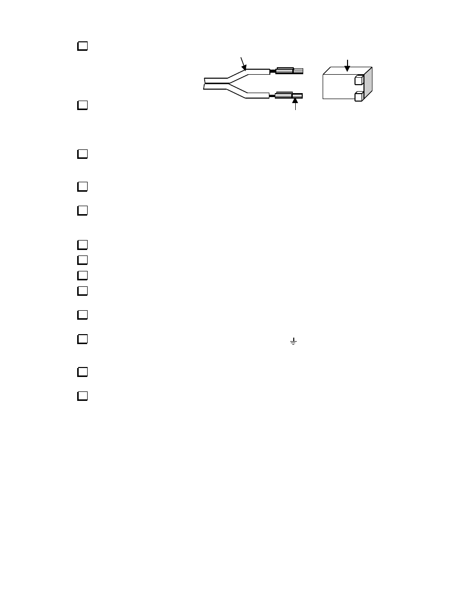
At one end of the speaker
cable, solder crimp pins to the two
wires as shown in Figure 5.
Pin 1 side
Copper wire
Crimp pin
Housing
Figure 5
Insert the copper wire into the pin 1 position of the two-pin housing as shown. Insert the other wire
into the pin 2 position. Note: The crimp pins should snap into place. Each pin has a very small tab on the
back that latches into a hole in the back side of the housing when inserted.
Connect the other end of this cable to the two terminals of the round replacement speaker. The copper
wire should be connected to the lug marked (+) on the speaker. Solder both wires.
Slide the neoprene washer over the speaker magnet. (See Figure 6, next page.)
Installation
Turn off the K1. Disconnect the antenna, power source, headphones, and key.
Remove the top and bottom covers. Unplug and remove the KAT1 (if applicable) and Filter board.
Plug the new speaker into P2 on the RF board. The 2-pin housing can only be plugged in one way.
Install the battery/speaker bracket as shown in Figure 6. The notches at either end of the bracket slide
over the tops of the pressed-in 10-32 nuts located on each K1 side panel.
Place the battery holder (without any batteries) in the indicated position, with its leads towards the
front. Insert the speaker into the large round hole in the bracket. Press the speaker down as far as it will go.
On the RF board near the power switch you'll find a ground pad (
), which will not be used. To the
right is a pad labeled "AUX 12V" (see Figure 6). Insert the free end of the red wire into this 12V pad. Set
the K1 up on its left side. Solder the wire on the bottom side of the RF board, and trim excess lead length.
Near the key jack are three wire pads labeled "DOT", "DASH", and "GND" on the bottom side of the
RF board. Insert the black wire into the GND pad. Solder and trim the wire.
Route the red and black wires as shown in Figure 6. Keep them close as possible to the side panel and
the nearby Filter board standoff. Final routing will be done with the Filter board in place.