Elecraft KBT1 Manual User Manual
Page 5
5
Install the switch onto the two screws (Figure 3B). Make sure the two washers which have already
placed on each screw stay between the switch frame and the bracket.
Secure the switch to the bracket using one additional #4 split lock washer and one 4-40 nut on each
screw. Do not over-tighten.
Cut an 8" (20 cm) length of red hookup wire. Remove 1/4" (6 mm) of insulation from each end. Twist
the strands tightly together at both ends, then tin each end using a very small amount of solder.
Wrap one end of the red wire around the unused switch terminal (Figure 3B). Make sure the wire is
not contacting the adjacent switch terminal or diode lead, then solder.
Cut a 4.5" (11.5 cm) length of black hookup wire. Prepare the ends as you did with the red wire.
Form one end of the black hookup wire into a small hook. Do the same to the black lead of the battery
holder. Attach the two hooks together securely, then solder.
Cut a 1" (2.5 cm) length of heat-shrink tubing, then slip it over the joint between the two black wires.
Shrink it using a heat gun or a soldering iron (not the tip--use the thicker part, about 1" from the tip).
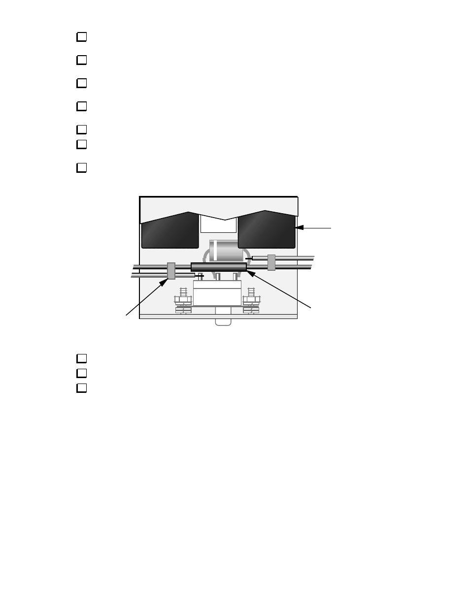
Neoprene
spacer (2)
Cable tie (2)
Heatshrink tubing
Red
Black
Red
Black
To RF board
From battery holder
Figure 4
Solder the battery holder's red wire to the anode (non-banded) end of D1 as shown in Figure 4.
Position the black wires and heatshrink tubing as shown above. Secure all wires using two cable ties.
Attach the two self-adhesive neoprene spacers at approximately the locations shown. The spacer on
the right may be touching the body of D1.