Bolted dead load anchors – EFCO S5500 Outside Glazed User Manual
Page 19
EFCO CORPORATION 6/2012
PART NO. Y550
Series 5500 Outside Glazed Installation Instructions
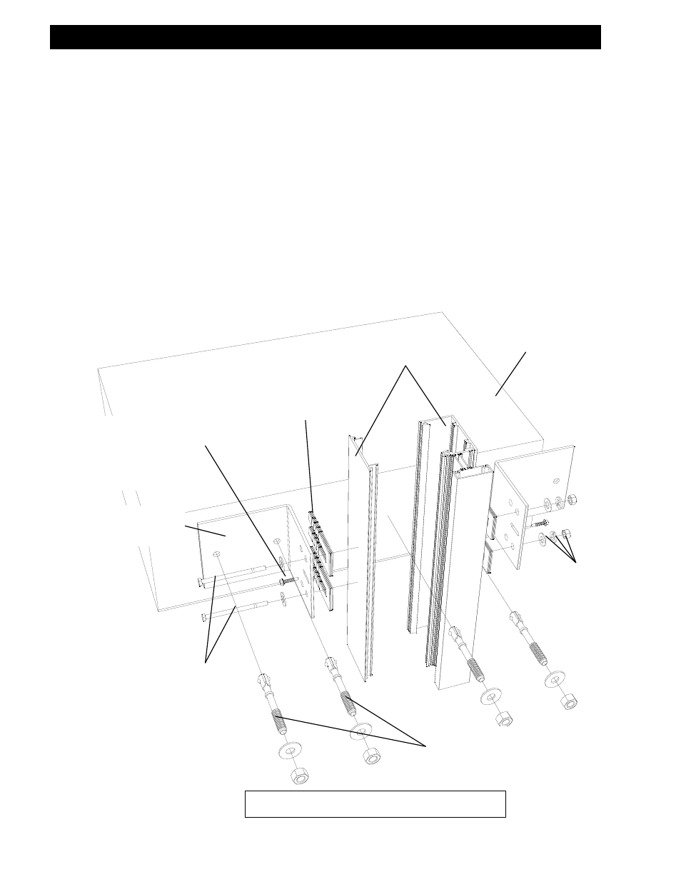
STEP #8 INSTALL FRAME COMPONENTS – BOLTED DEAD LOAD ANCHORS
For installations with multi-spans, follow applicable notes from step 9. When the frame is properly
aligned, and is level and plumb, match drill the slab through the anchor and install anchor bolts se-
curing the anchor to the building structure. Match drill the mullion through the set of holes in the
anchor.
NOTE: The holes must be a minimum of 1” from the back of the mullion in order to clear any steel re-
inforcement located inside the system, as may be required on a job specific basis.
Refer to the approved shop drawings for anchor bolt size, type, spacing, and embedment as well as
anchor dimensions.
NOTE: For special instructions regarding wind load anchors, see page 21, step 9.
FRAME UNITS
HIGH IMPACT
POLYSTYRENE
HORSESHOE SHIMS
AT EACH BOLT
STEEL ANCHOR PER
SHOP DRAWINGS
TEMPORARY
ALIGNMENT
SCREW (#12 X 1”
TEK SCREW)
BOLTS WITH
FLAT WASHERS
BOLTED DEAD LOAD ANCHORS
ANCHOR BOLTS
AS REQUIRED
FLAT AND SPRING
LOCK WASHERS
AND NUTS
BUILDING
STRUCTURE
Section III: Typical Anchorage Methods