Connecting the dynoware ex – Dynojet Snowmobile Dynos: Installation Guide User Manual
Page 17
Document #98226100
Master
2 - 5
Document #98226100
Master
2 - 5
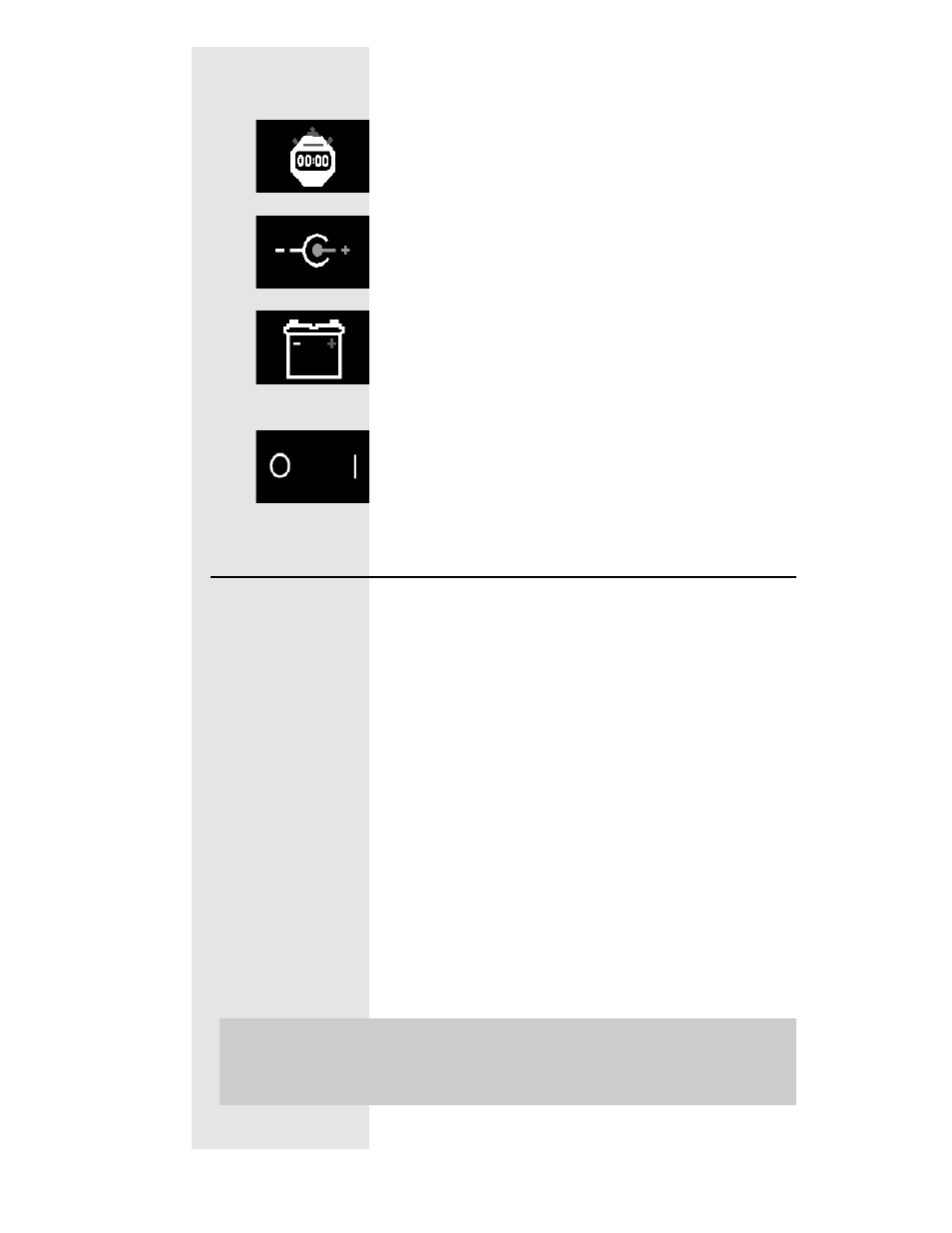
CPU Module:
..... Continued
This connector provides a synchronization signal
to a 3rd-party data acquisition system.
This connector provides 12 Volt DC power to a
3rd-party data acquisition system.
This connector accepts 12 Volt DC power from a
power supply or battery.
The adjacent LED
glows bright green when power is properly
connected.
When this switch is on, power is supplied to all
connected modules.
Connecting the DynoWare EX+
Use the cables that came in the DynoWare
package to make the following connections:
• 9-pin shielded serial cable between the RS-232
connector of the CPU Module and a free COM
(serial communications) port on the PC. A 9-
pin to 25-pin adapter may be required at the
PC.
• 25-pin shielded cable from the dynamometer to
the Dynamometer Input/Output Module.
• 9-pin connector from the hand held pendant to
the Dynamometer Input/Output Module.
• 3-pin plug from the power supply to the CPU
Module with its flat side facing down.
(Refer to the picture on the next page)
Note:
The DynoWare EX+ stack must be
mounted in your shop so as to be easily
seen while making dyno runs.