Memory installation, Ibm p550, Figure 1 figure 2 – Dataram DRI520P6 User Manual
Page 2
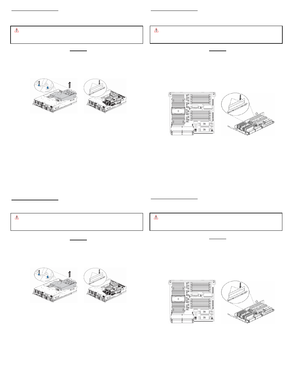
MEMORY INSTALLATION
Note: Refer to your system owner’s manual for detailed instructions.
MEMORY INSTALLATION
Note: Refer to your system owner’s manual for detailed instructions.
IBM P520
(Models E4A, M15, and M25)
•
Shut down and unplug the system, then remove the cover.
•
Remove air baffle and fans by lifting the 4 tabs and lifting the baffle
out of the system (See Figure 1).
Figure 1 Figure 2
•
Each system has 8 memory module slots. The memory modules
should be installed in the order listed in your user guide.
•
Remove the memory module fillers if present.
•
Ensure that the connector locking tabs are in the unlocked position.
•
Align the memory module notch with the key in the connector to
ensure that the module is installed properly and not damaged.
•
Push the memory module firmly into the connector until the locking
tabs engage (See Figure 2).
•
Replace the air baffle and put the cover back on.
Caution: System parts are sensitive to electrostatic discharge and can be
damaged by the static charge you may carry. You should wear a
grounded wrist strap.
Caution: System parts are sensitive to electrostatic discharge and can be
damaged by the static charge you may carry. You should wear a
grounded wrist strap.
IBM P550
(Model M50 and E8A)
•
Shut down and unplug the system, then remove the cover.
•
Remove the system processor assembly by lifting the handles up
and pulling it out of the system, and place it on a static-free surface.
•
Each processor assembly has 8 memory slots. The memory
modules should be installed in the order listed in your user guide.
•
The numbering scheme is listed in Figure 1 below.
Figure 1 Figure 2
•
Remove the memory module fillers if present.
•
Ensure that the connector locking tabs are in the unlocked position.
•
Align the memory module notch with the key in the connector to
ensure that the module is installed properly and not damaged.
•
Push the memory module firmly into the connector until the locking
tabs engage (See Figure 2).
•
Replace the air baffle and put the cover back on.
MEMORY INSTALLATION
MEMORY INSTALLATION
Note: Refer to your system owner’s manual for detailed instructions.
Note: Refer to your system owner’s manual for detailed instructions.
IBM P520
(Models E4A, M15, and M25)
•
Shut down and unplug the system, then remove the cover.
•
Remove air baffle and fans by lifting the 4 tabs and lifting the baffle
out of the system (See Figure 1).
Figure 1 Figure 2
•
Each system has 8 memory module slots. The memory modules
should be installed in the order listed in your user guide.
•
Remove the memory module fillers if present.
•
Ensure that the connector locking tabs are in the unlocked position.
•
Align the memory module notch with the key in the connector to
ensure that the module is installed properly and not damaged.
•
Push the memory module firmly into the connector until the locking
tabs engage (See Figure 2).
•
Replace the air baffle and put the cover back on.
Caution: System parts are sensitive to electrostatic discharge and can be
damaged by the static charge you may carry. You should wear a
grounded wrist strap.
Caution: System parts are sensitive to electrostatic discharge and can be
damaged by the static charge you may carry. You should wear a
grounded wrist strap.
IBM P550
(Model M50 and E8A)
•
Shut down and unplug the system, then remove the cover.
•
Remove the system processor assembly by lifting the handles up
and pulling it out of the system, and place it on a static-free surface.
•
Each processor assembly has 8 memory slots. The memory
modules should be installed in the order listed in your user guide.
•
The numbering scheme is listed in Figure 1 below.
Figure 1 Figure 2
•
Remove the memory module fillers if present.
•
Ensure that the connector locking tabs are in the unlocked position.
•
Align the memory module notch with the key in the connector to
ensure that the module is installed properly and not damaged.
•
Push the memory module firmly into the connector until the locking
tabs engage (See Figure 2).
•
Replace the air baffle and put the cover back on.