B&M 80885 HAMMER SHIFTER User Manual
Page 3
3
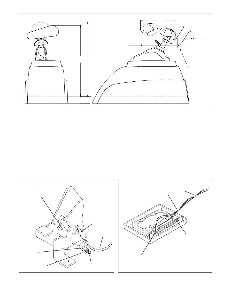
Remove this blocker pin and
the two e-clips for GM four
speed transmissions
Figure 3
into the front hole on the selector lever.
Tighten the large nuts completely. Be sure
that the swivel will slide freely in and out of the
hole in the selector lever. Note: The shifter
will not operate correctly unless the front
hole in the shift lever is used.
Leave the swivel out of the hole and move
the selector lever to PARK, all the way for-
ward. Also move the shifter to PARK position
(all the way forward). Reinsert the swivel into
the front hole in the selector lever. Check to
see that the swivel will slide freely in and out
of the front hole in the selector lever in this
position. If it does not slip in freely, adjust the
swivel slightly until it will slip into the hole in the
lever.
Move the shifter back to the low gear
position and check that the swivel will still slide
easily in and out of the front hole in the selector
lever. (If you do not use the front hole in the
lever, it will be impossible to correctly adjust
the cable.) Operate shifter through all gear
positions. Check to make sure swivel will slide
in and out of the front selector lever hole in
each gear position. The shift cable is now
correctly adjusted. Install cotter key supplied
with shifter into swivel and spread key ends.
If you have a problem, DO NOT FORCE
THE SHIFTER, this will damage the cable,
the shifter or the transmission. Simply start at
the beginning and carefully check all your
steps.
STEP 14. On GM vehicles the neutral safety
switch may be located on the shifter (steering
column or console), or it may be a mechanical
interlock in the steering column that prevents
the key from turning to the Start position
unless the shifter is in the Park or Neutral
position. Identify the type of neutral safety
system you have. If the key will not turn to the
Start position unless the stock shifter is in
Park or Neutral, you have a mechanical inter-
lock type, otherwise you have a neutral safety
switch type. If you have a neutral safety
switch, locate the switch and identify the
neutral safety wires (engine will not crank
unless these wires are connected together).
With either type, disconnect battery ground
cable to prevent accidental shorts. If you have
a neutral safety switch, disconnect and ex-
tend both wires from the GM switch to the
Figure 2
Figure 4
Tape wires to indicator cable
close to cable bracket and
about 4" further along cable
Adjust indicator
cable bracket to
center LED indicator
Slide indicator all the way in this
direction. Leave a little slack in wires.
10.36
6.64
1.00
Trim as
required
10.50
6.30
E-Ring
Indicator
cable
Sheet metal
screw (2)
Bracket
Washer (2)