B&M 80885 HAMMER SHIFTER User Manual
Page 2
2
STEP 8.
Install shifter mechanism into ve-
hicle. Slide shifter cable through carpet and
hole in floor. Bolt shifter down using four 1/4"
x 1-1/2" hex bolts and nuts. If required use 1/
4" washers as shims between the shifter
mechanism and floor to level shifter. ROUTE
CABLE AS SHOWN IN FIGURE 5, AVOID
SHARP BENDS WHICH WILL KINK AND DAM-
AGE CABLE. Use cable clamps or tie wraps
to secure the cable housing to chassis to avoid
contact with hot engine or exhaust system.
STEP 9.
Seal the hole where the cable goes
through the floorboards to prevent air or water
leakage. A putty type sealer can be used. For
General Motors vehicles go to Step 10, for
Ford vehicles got to Step 15, For Chrysler
vehicles go to Step 21.
GENERAL MOTORS
STEP 10. If you have not already done so,
remove the stock selector lever nut and selec-
tor lever from the transmission. Discard stock
lever and stock shifter linkage. Install B&M
selector lever in position using stock selector
lever nut, (See figure 6). Torque nut to 23 lb.
ft. The lever should move smoothly from front
to rear with a positive click in each gear
position.
STEP 11. Remove two transmission oil pan
bolts from the middle of the left side of the oil
pan. Install cable bracket in position, (See
figure 6.) The bracket must be installed with
two spacers between the pan and bracket. (If
your transmission is equipped with a cast
aluminum oil pan, these spacers should be
omitted. With a TH-400 with a cast aluminum
oil pan the cable bracket may have to be
modified.) Install the two 5/16-18 x 1.00" bolts
(Metric transmissions use the two 8mm x
25mm bolts) supplied and tighten 12-13 ft.
lbs. Do not overtighten as this can damage
pan gasket.
Note: In some cases possible modifica-
tion to the GM cable bracket might be
required for the 4L80E and 4L85E trans-
missions without the PRNDL switch.
Verify that selector lever does not grind
on cable bracket before moving on to
step 10.
STEP 12. Route the shifter cable according to
figure 5. Avoid kinks and sharp bends and
route the cable away from hot engine or
exhaust parts.
Remove the two rubber boots, one large
nut, and a large lockwasher from the threaded
end of the shifter cable. Slide the end of the
cable into the cable bracket, Install large nut
and lockwasher loosely over end of cable.
Install two rubber boots onto end of cable.
Install the swivel on the threaded end of the
cable and position it in the center of the
threaded portion.
STEP 13. Move the transmission selector le-
ver by hand to full rear position (LOW). Oper-
ate the shifter lever to the low gear position
(ratcheted all the way back). Adjust the large
nuts on the cable so that the swivel will slide
wire must be connected to a source that is hot
when ever the ignition is turned on, since the
shifter indicator will not be visible, even in
daylight, unless it is illuminated. The ground
wire can usually go to one of the bolts that hold
the shifter to the floor. The hot wire will
probably have to go to the instrument panel.
After the wires are lengthened, slide the
indicator in the shifter top plate all the way to
the rear, the end away from the cable connec-
tion. Then tape the two wires to the indicator
cable just ahead of the cable mounting bracket.
Leave a little slack in these wires with the
indicator all the way to the rear. About 3”
further down the cable tape the wires to the
cable again. See figure 4.
Secure the indicator cable bracket to the
shifter mechanism with two #6 x 1/4" sheet
metal screws and #6 washers. (Do not use
longer screws in this position or they will
cause the mechanism to bind.) The eyelet on
the end of the indicator cable is secured to the
cable pin by a supplied small E-Ring, as shown
in figure 3.
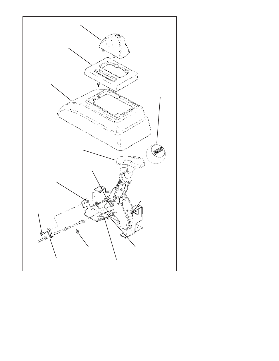
Figure 1
Remove this
blocker
pin and the two e-clips
for GM four speed
transmissions
Cable pin
Boot
Top plate
Tower
1/4" nut
1/4" lockwasher
1/4" x 1/2"
bolt
Cable attaching tab goes on
outside surface of shifter base
E-Ring
Neutral safety
switch
switch
Back-up light
Shifter #80885
Shifter #80887