Operation, 3 spd std gate 3 spd rev gate – B&M 80706 PRO STICK SHIFTER User Manual
Page 7
completely. Be sure that the swivel will slide freely in and out
of the hole in the selector lever. Note: The shifter will not op-
erate correctly unless the hole marked “H” in the shift lever
is used.
Leave the swivel out of the hole and move the selector lever
to the Park position (all the way forward). Reinsert the swivel
into the hole marked “H” in the selector lever. Check to see
that the swivel will slide freely in and out of the hole marked
“H” in the selector lever in this position. If it does not slip in
freely, adjust the swivel slightly until it will slip into the hole
marked “H” in the lever.
Move the shifter back to the Low gear position and check that
the swivel will still slide easily in and out of the hole marked
“H” in the selector lever. (If you do not use the hole marked
“H” in the lever, it will be impossible to correctly adjust the
cable.) Operate the shifter through all the gear positions. Check
to make sure the swivel will slide in and out of the hole marked
“H” selector lever hole in each gear position. The shift cable
is now correctly adjusted. Install the cotter key supplied with
the shifter into the swivel and spread the key ends.
If you have a problem, DO NOT FORCE THE SHIFTER, this
will damage the cable, the shifter, or the transmission. Simply
start at the beginning and carefully check all your steps.
Step 36. Disconnect the battery ground cable to prevent acci-
dental shorts. Identify the neutral safety wires (engine will not
crank unless these wires are connected together). Extend the
wires to the shifter. Strip 1/4” insulation off the wires and
install slip-on terminals supplied in kit. Crimp the terminals
onto the wires using a crimping tool or pliers. Connect the
neutral safety wires to the LOWER switch and the backup
light wires to the UPPER switch (See Figure #1). Tape the
terminal connections and all other connections to prevent
shorts.
Reconnect the battery ground cable, disconnect the coil wire
and set the parking brake. Check the switch operation by
attempting to start the motor in each shifter position. The
starter must crank only when the shifter is in the Park or
Neutral position. Check the backup light operation when the
shifter is shifted to the Reverse position. Adjust the switches
if required. Reconnect the coil wire.
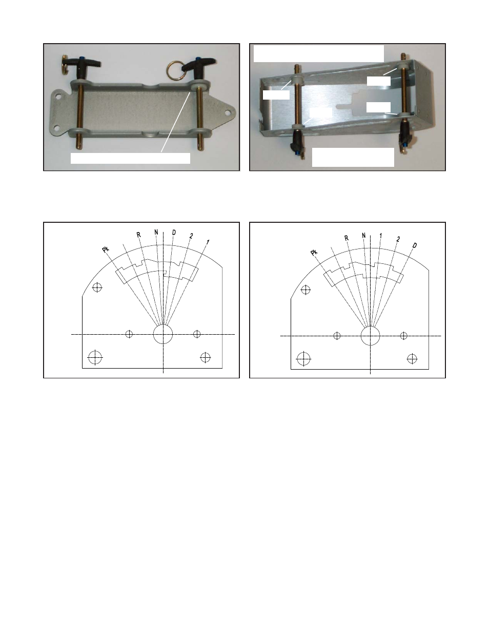
Figure #11
Figure #12
Use epoxy to attach spacer here
Use epoxy to attach 4
spacers as shown
1 Thick
1 Thin
1 Thin
1 Thin
Spacers required when using cover
without quick release bracket
OPERATION
How to shift Pro Stick Shifter
Note: The Reverse Lockout Lever (See Figure #1) described in the following instructions ONLY needs to be operated when shifting from Neutral to Reverse
3 Spd Std Gate
3 Spd Rev Gate
Figure #13
Figure #14
7