B&M 70298 HI TEK COOLING SYSTEM User Manual
Page 2
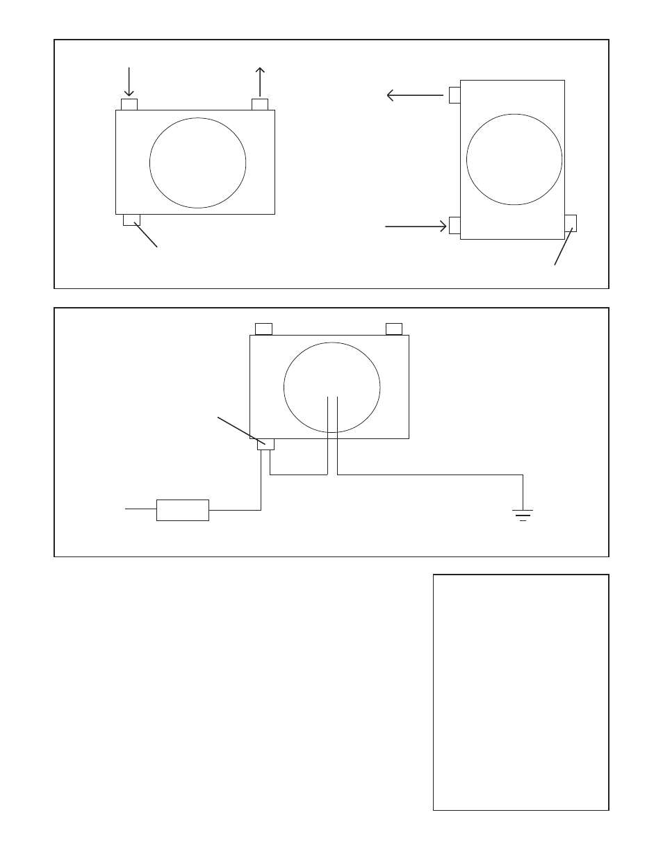
OR
IN
OUT
Cooler
Thermal Switch
Cooler
IN
OUT
Thermal Switch
PARTS LIST
1 Hi-Tek Cooling System
1 Electrical Connector
TOOL LIST
1/2" tubing or open-ended wrench
9/16" tubing or open-ended wrench
5/8" tubing or open-ended wrench
electrical fitting crimper
FIGURE 1
Fan
Fan
Cooler
Thermal Switch
Fan
15A Fuse
+12V
Note: As a suction fan the air is to be pulled through the cooler. This should be verified to ensure correct polarity.
FIGURE 2
Colored Wire
Black Wire
STEP 2. Wire the thermal switch and
fan as indicated in figure 2. Verify that
the fan pulls air through the cooler. If it
doesn't reverse polarity.
STEP 3. After installation, check oil
levels and fill as necessary. For engine
oil, start the engine and allow it to idle
for a few minutes. Turn the engine off
and then after a few minutes check the
oil level again and fill as required but do
not over fill as this will causing foaming.
For automatic transmission oil, apply
the parking brake, start the engine and
place the shifter in the neutral position.
The automatic transmission fluid level
must be checked with the engine run-
ning and the fluid hot. Add fluid as
required but do not over fill as this will
cause foaming and overheating.
STEP 4. Check all of the hoses and
fittings for leaks. Secure the hoses so
that they won't be damaged by road
debris or other hazards. RECHECK
PERIODICALLY.