B&M 46076 LAUNCH CONTROL KIT User Manual
Page 4
insulated connector. All soldered
connections should be wrapped with
plastic electrical tape. All wires should
be as short and direct as possible, but
not short enough to put any tension
on the wires. Electrical wires should
not be under tension even when the
engine and transmission move on the
their mounts.
Step 1. Disconnect the negative
battery cable.
Step 2. A momentary push button
switch is supplied and may be
mounted in any convenient position.
You may want to use the B&M T-
Handle with push button (#80659
chrome or #80658 brushed aluminum)
or the push button knob (#46112),
These knobs and T-Handles will fit
most S.A.E. sizes of shifter stick
threads.
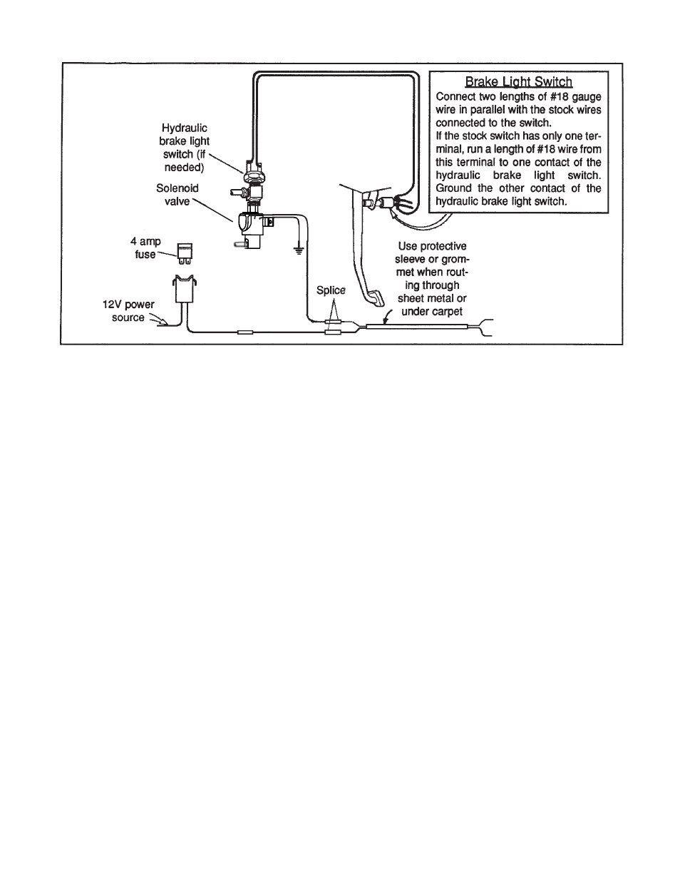
Step 3. Run a length of 18 gauge wire
from the end of the switch cable to
the solenoid valve(s). At the solenoid
valve(s) splice the newly installed wire
to one lead of the solenoid(s), ground
the other solenoid lead(s).
Step 4. Connect one end of the fuse
holder to a switched ignition terminal.
Run a length of 18 gauge wire from
the other end of the fuse holder to the
other wire of the switch cable. Splice
this wire at both ends.
Step 6. Connect the battery. The
solenoid valve(s) should operate
when the push button is depressed.
If the fuse blows out there is a short
circuit. Check all of the splices and
connections to be sure they are
insulated and that there are no short
circuits.
Step 7. Apply the brakes hard, push
and hold the launch control button and
release the brakes. Have someone
check to see if the brake lights remain
on. If the lights go out it will be
necessary to add an additional
hydraulic brake light switch. The
switch should be installed on the
brake side of the solenoid valve, as
shown in the illustration. The two
terminals of the new brake light switch
should be wired in parallel with the
existing brake light switch.
OPERATION
Pressing and holding the launch
control push button switch energizes
the solenoid valve. When the brake
pedal is pushed the hydraulic
pressure applies all four brakes. When
the brake pedal is released the
pressure is retained the solenoid valve
on the wheels that are controlled by
the launch control, while the pressure
is released on the other wheels. When
the push button is released the brakes
that were held on by the launch control
are released and the vehicle can
accelerate. After the installation, but
before driving the vehicle, check the
brake system thoroughly for leaks and
be sure that you have a solid brake
pedal. Apply the launch control
several times and be sure that the
wheels that are supposed to be locked
are locked and that the brakes are free
when the launch control is released.
After the installation has been
completed bleed the entire brake
system thoroughly to eliminate all air
in the system. Check all connections
for leakage under pressure and be
sure you have a hard brake pedal, not
a soft pedal. Replace any brake fluid
lost by the installation or by bleeding
with heavy duty brake fluid marked
DOT 3 or DOT 4.
For most automatic transmission
shifters we recommend that you use
the B&M T-Handle with push button
(#80659 chrome or #80658 brushed
aluminum) or the push button knob
(#46112). These knobs and T-
Handles will fit most sizes of stick
threads. B&M also offers remote
buttons with spiral cord #46003 and
#46013.
4
To supplied or
other switch