B&M 40227 TRANSPAK User Manual
Page 4
VALVE BODY MODIFICATIONS
IMPORTANT HINT: The spring clips
at the end of the valve body bores can
fly off during removal. To prevent
losing the spring clips place a small
rag over the clip when removing it,
this will help prevent the clip from
flying off and becoming lost. B&M
does not stock replacement spring
clips. If yours are lost or damaged see
your local Ford parts supplier or try a
transmission shop.
STEP 5. Heavy Duty and Street;
Pressure regulator. Remove the re-
taining clip at the end of the pressure
regulator bore (See Fig. 4) Use a
screwdriver to hold the pressure regu-
lator assembly in while removing the
retaining clip. If the sleeves stick in
the bore, lightly punch the sleeve with
a small rod and a mallet allowing it to
snap back out of the bore. Remove
Sleeve with Boost Valve and the out-
ermost pressure regulator spring. Re-
place the stock outer pressure regula-
tor spring with the RED spring sup-
plied in the kit. Reassemble pressure
regulator in reverse order of disas-
sembly.
STEP 6. Heavy Duty Only; 1-2 Ca-
pacity Modulator. Remove the spring
clip at the end of the 1-2 Capacity
Modulator bore (See Fig. 4). Remove
the bore plug, 1-2 Capacity Modulator
valve and spring from bore. On later
model valve bodies use the M4x40
(4mm metric screw supplied in kit) in
tapped hole to assist removing bore
plug. Early valve bodies do not have
a hole in the bore plug so you will have
to pry the plug out with a small screw
driver. Replace the stock spring with
the YELLOW spring supplied in kit.
Reassemble spring, valve and bore
plug (tapped hole facing out) and
install spring clip.
STEP 7. Street Only; 1-2 Capacity
Modulator. Remove the spring clip
at the end of the 1-2 Capacity Modu-
lator bore (See Fig. 4). Remove the
bore plug, 1-2 Capacity Modulator
valve and spring from bore. On later
model valve bodies screw the M4x10
(4mm metric screw supplied in kit) in
tapped hole to assist removing bore
plug. Early valve bodies do not have
a hole in the bore plug so you will have
to pry the plug out with a small flat
screw driver. Replace the stock spring
with the GREEN spring supplied in
kit. Reassemble spring, valve and
bore plug (tapped hole facing out) and
install spring clip.
SEPARATOR PLATE
MODIFICATIONS
IMPORTANT: The B&M AOD sepa-
rator plate was designed to work with
any of the three versions of AOD
valve bodies produced between 1980
and 1990. The following steps explain
how to set up the B&M AOD separator
plate for your particular model valve
body.
STEP 8. Place the stock separator
plate on top of the B&M plate with the
valve body side of the plates facing
up. Install (2) of the short reinforce-
ment plate screws and nuts (supplied
in kit) through the alignment holes as
4
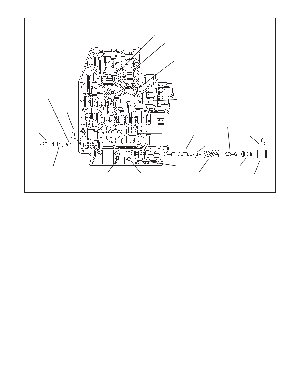
#2
#3
#4
#5
#6
#1 orange
check ball
Note: #2 through #8
check balls are black
rubber.
#7 checkball is not used.
Boost valve
Pressure regula-
tor valve
Retainer
Retaining clip
Retaining
clip
Figure 4
Inner pressure
regulator spring
#8
Short stem TV pres-
sure relief valve
(green spring)
Converter relief valve,
long stem (green or
blue spring)
Replace stock outer pres-
sure regulator spring with
red spring in kit. See step 5.
Boost valve
sleeve
1-2 Capacity modu-
lator valve. Inslall in
furthest bore in this
direction,
Bore plug
(tapped hole
faces out)
Replace stock spring
with spring from kit.
See steps 6 or 7