Making the connections, ภาษ าไทย – AVer CP355 user manual User Manual
Page 9
English
繁體中文
简体中文
日本語
ภาษ
าไทย
M
M
a
a
k
k
i
i
n
n
g
g
t
t
h
h
e
e
C
C
o
o
n
n
n
n
e
e
c
c
t
t
i
i
o
o
n
n
s
s
(2)
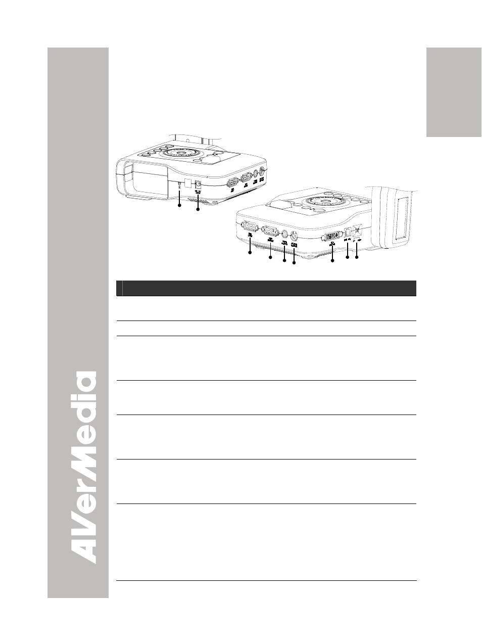
The ports on the rear, left and right panel of CP355 enable you to
connect the unit to a computer, graphics display monitor or LCD/DLP
projector, TV or other device. Illustrated below are the ports that are
located at the rear, left and right panel of CP355 with their corresponding
labels.
(1)
Right Panel
(4) (5)(6)
(8)
(3)
(9)
Rear & Left Panel
(7)
Port
Description
(1) Antitheft Slot
Attach a Kensington compatible security lock or
antitheft device.
(2) DC 12V Input
Connect the power adapter into this port.
(3) RGB INPUT
Input the signal from a computer or other sources
and pass it through to the RGB Output port only.
Connect this port to the RGB/VGA output port of the
computer.
(4) RGB OUTPUT
Output the signal from the camera, RGB input port,
or the captured images from the memory on a
CRT/LCD/MAC monitor or LCD/DLP projector.
(5) VIDEO OUTPUT
(RCA/Composite)
Output the signal from the camera or the captured
images from the memory on TV or Video
equipment. Connect this port to the VIDEO input
port of a TV or video equipment.
(6) S-VIDEO
OUTPUT
Output the signal from the camera or the captured
images from the memory on TV or Video
equipment. Connect this port to the S-VIDEO input
port of a TV or video equipment.
(7) DVI-I OUTPUT
Output the signal from the camera, RGB input port,
or the captured images from the memory on a
CRT/LCD/MAC monitor or LCD/DLP projector with
DVI-I interface.
If the display device does not support DVI-I, it can
only display the signal from the camera and the
captured images.
5