4c 4e 4d – Alumax P-DRC1Y User Manual
Page 20
20
4
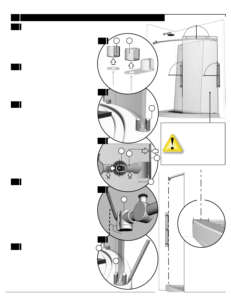
FIXED PANEL PLACEMENT
ENSURE THAT THE FIXED
PANEL AS WELL AS THE
RUNNING RAIL ARE LEVEL
DURING THESE PROCEDURES.
Begin by removing the bottom glass clip’s
and bottom guide’s fixed panel retainers
(11) (12) from their assembly.
4A
Position the bottom glass clip (11) and
bottom guide (12) on fixed panel (7) as
4B
Ensure that the running rail (1) is at the
highest possible position in reference to the
holes of the fixed panel (7). Adjust the fixed
panel (7), by way of the running rail (1), so
as to force the gasket (10) against the wall.
The distance between the fixed panel and
wall should approximately be 3/16”.
4C
4E
4D
Mark the locations for the wall brackets (2)
on the walls on both sides of shower.
The door side wall bracket (2) should be
placed at 5/16” (8mm) from the center line
of the base threshold.
4E
Mark the fixed panel retainers’ locations on
the base (11) (12).
2
1/2’’ 12.7mm
3/16’’
12
11
12
4
1
7
10
CENTER OF BASE THRESHOLD
4A
4B
4C
4D
4E
11
12
- 300c (9 pages)
- 300cv (8 pages)
- 300d (9 pages)
- 338 (9 pages)
- 340 (9 pages)
- 340 Deluxe (9 pages)
- 390c Supplement (5 pages)
- 390cv Supplement (4 pages)
- 391 (12 pages)
- 392 (11 pages)
- 393 (11 pages)
- 394 (11 pages)
- 640S (8 pages)
- 640 (8 pages)
- 640D (7 pages)
- 641 Side Panel (6 pages)
- 694 (6 pages)
- 700c (7 pages)
- 733 (8 pages)
- 738 (8 pages)
- 738 Towel Bar (1 page)
- 740D (8 pages)
- 790c Supplement (4 pages)
- 791 (11 pages)
- 792 (12 pages)
- 793 (12 pages)
- 793 Buttress Supplement (1 page)
- 794 (11 pages)
- 794s (9 pages)
- 795 (10 pages)
- 890 (9 pages)
- 890c (8 pages)
- 1040 (9 pages)
- Deluxe Towel Bar (1 page)
- Transportation Latch (1 page)
- DesignLine Hinge (5 pages)
- P-DR1W-48-60 (14 pages)
- P-DR1W-72 (15 pages)
- P-DR1WT-60 (14 pages)
- P-DR2W-48-60-CRP (18 pages)
- P-DR2W-48-60-CW (19 pages)
- P-DR2W-72-CRP (19 pages)
- P-DR2W-72-CW (19 pages)
- P-DR3W-60 (32 pages)
- P-DRA1Y (16 pages)