Snapshot interface – Achronix Speedster22i Snapshot User Manual
Page 7
Snapshot Interface
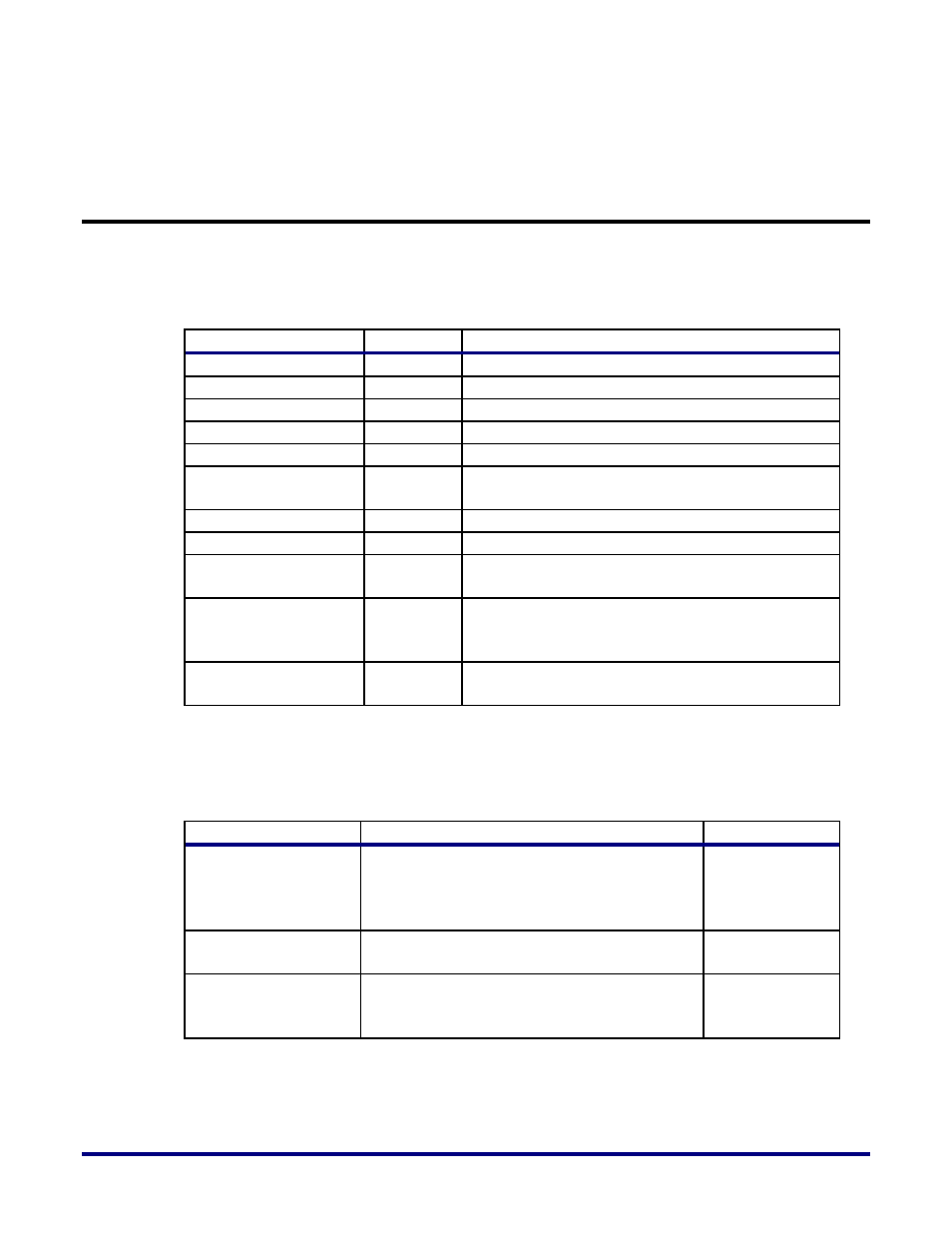
Below is the port list of the Snapshot macro:
Table 1: Pin Descriptions of Snapshot Macro
Pin Name
Type
Description
tck
Input
JTAG test clock
rstn
Input
JTAG test reset (active low)
tdi
Input
JTAG test data in
tms
Input
JTAG test mode select
tdo
Output
JTAG test data out
Monitor_ch
[MNTR_WIDTH-1:0]
Input
36-144 bit tapped user logic data bus
trigger_ch [35:0]
Input
36-bit trigger channel data
usr_clk
Input
User clock (same as user design clock)
Rstn_out*
Output
Reset output to reset user’s logic block if needed.
Otherwise, the user can leave this pin floating
Arm*
Output
Asserted when Snapshot logic starts observing the
monitor channels and trigger values. De-asserted
when Snapshot logic is reset via the GUI.
Stimuli*
Output
Values output on this bus are set by the user via the
3rd trigger pattern value in the GUI.
*These outputs are in the “usr_clk” domain and can be used in the Design-Under-Test (DUT)
to create desired events to be observed.
Table 2: Parameter Defitions
Parameter
Defined Value
Default Value
MNTR_WIDTH
{36,72, 108, 144}
User-defined based on how many signals need
to be monitored in Snapshot. The captured
sample size will always be 1024.
144
DUTNAME
Field provided to the user to help distinguish
SnapShot logic instances in different devices
"none_specified"
OUTPUTPIPELINING
Add this many cycles of latency to the Arm
and Stimuli outputs to enable fast usr_clk
speeds
0
UG016, September 22, 2014
7