Exploded view, Installation and assembly – ProTemp PT-30P-DDF-A User Manual
Page 12
NEVER LEAVE A FAN
UNATTENDED WHILE
OPERATING OR WHILE
CONNECTED TO A POWER
SOURCE
© 2014, Pinnacle Products International, Inc.
12
HVF Air Circulator User’s Manual
24’’ OMNI DIRECTIONAL FAN: PT-24O-DDF
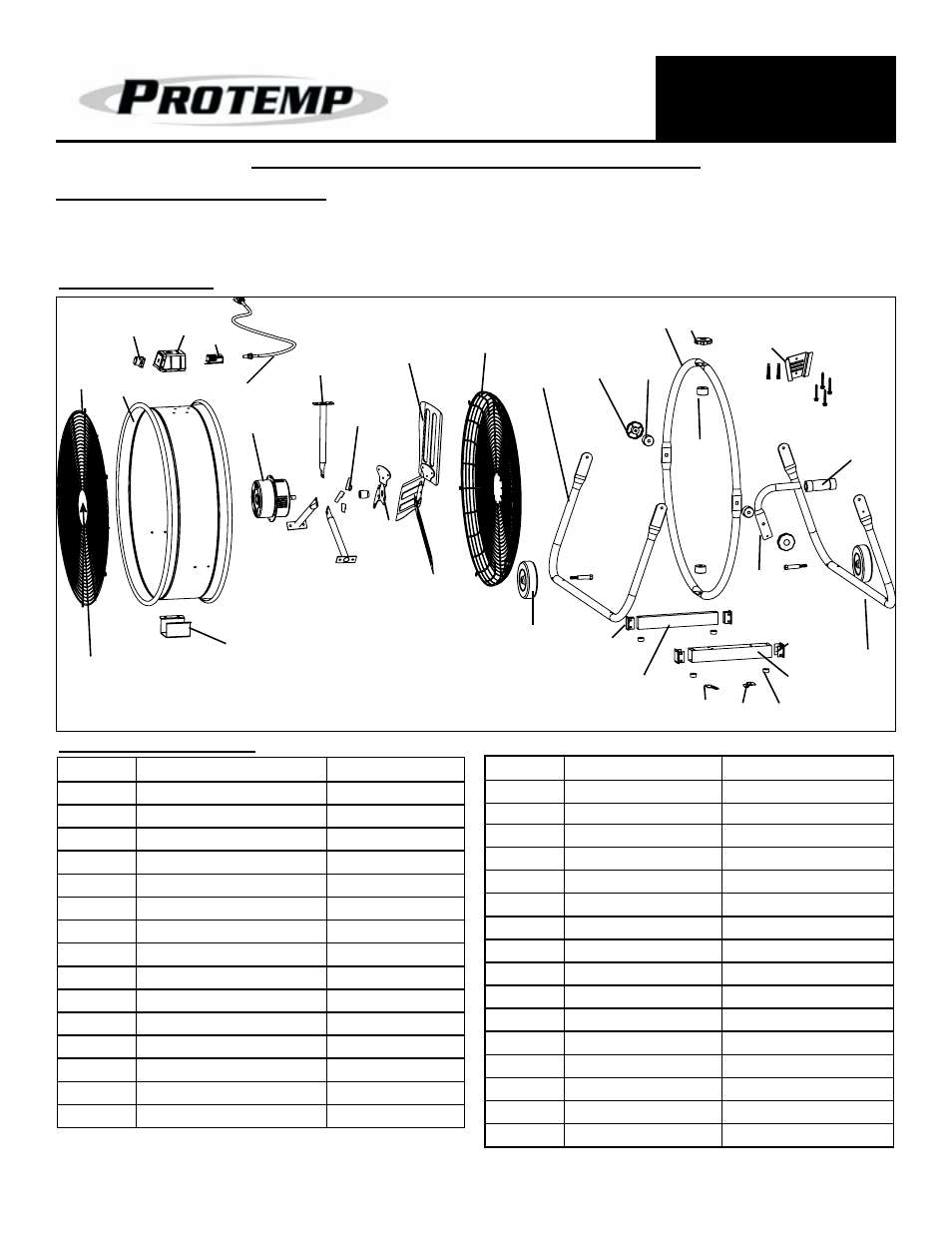
Replacement Parts
Item #
Description
Part Number
1
Front Guard
95-032-0170
2
Fan Barrel
95-001-0400
3
Power Knob
95-027-0130
4
Power Knob Holder
95-031-0325
5
Capacitor
95-004-0235
6
Power Cord
95-026-0255
7
Motor
95-030-0535
8
Motor Mount Assembly
95-030-0555
9
Motor Cooling Fan
95-030-0556
10
Fan Blade Assembly
95-003-0621
11
Rear Guard
95-032-0275
12
Front Leg
95-009-0600
13
Horizontal Adj. Knob
95-015-0150
14
Spacer
95-050-0200
15
Outer Ring Frame
95-024-0320
Item #
Description
Part Number
16
Vertical Adj. Knob
95-015-0150
17
Wall Mount
95-078-0200
18
Handle Pad
95-007-0100
19
Spacer
95-050-0200
20
Handle Arm
95-006-0300
21
Rear Leg
95-009-0610
22
Large Base Cap
95-024-0410
23
Large Base
95-024-0400
24
Foot Pad
95-023-0240
25
Wall Bracket - L
95-077-0100
26
Wall Bracket - R
95-077-0110
27
Small Base
95-024-0500
28
Small Base Cap
95-024-0510
29
Wheel
95-004-0155
30
Lower Mount
95-024-0325
31
Logo Plate
95-043-0331
Exploded View
1
2
3
4 5
7
8
9
10
11
12
13
14
16
19
17
18
21
20
22
23
25
26
27
Figure 11: Exploded View of: PT-24O-DDF
28
24
29
30
15
6
31
Installation and Assembly
1. Place the fan on level ground in a safe, desired position
then connect to an approved power source.