CH Tech EM405D User Manual
Page 15
9
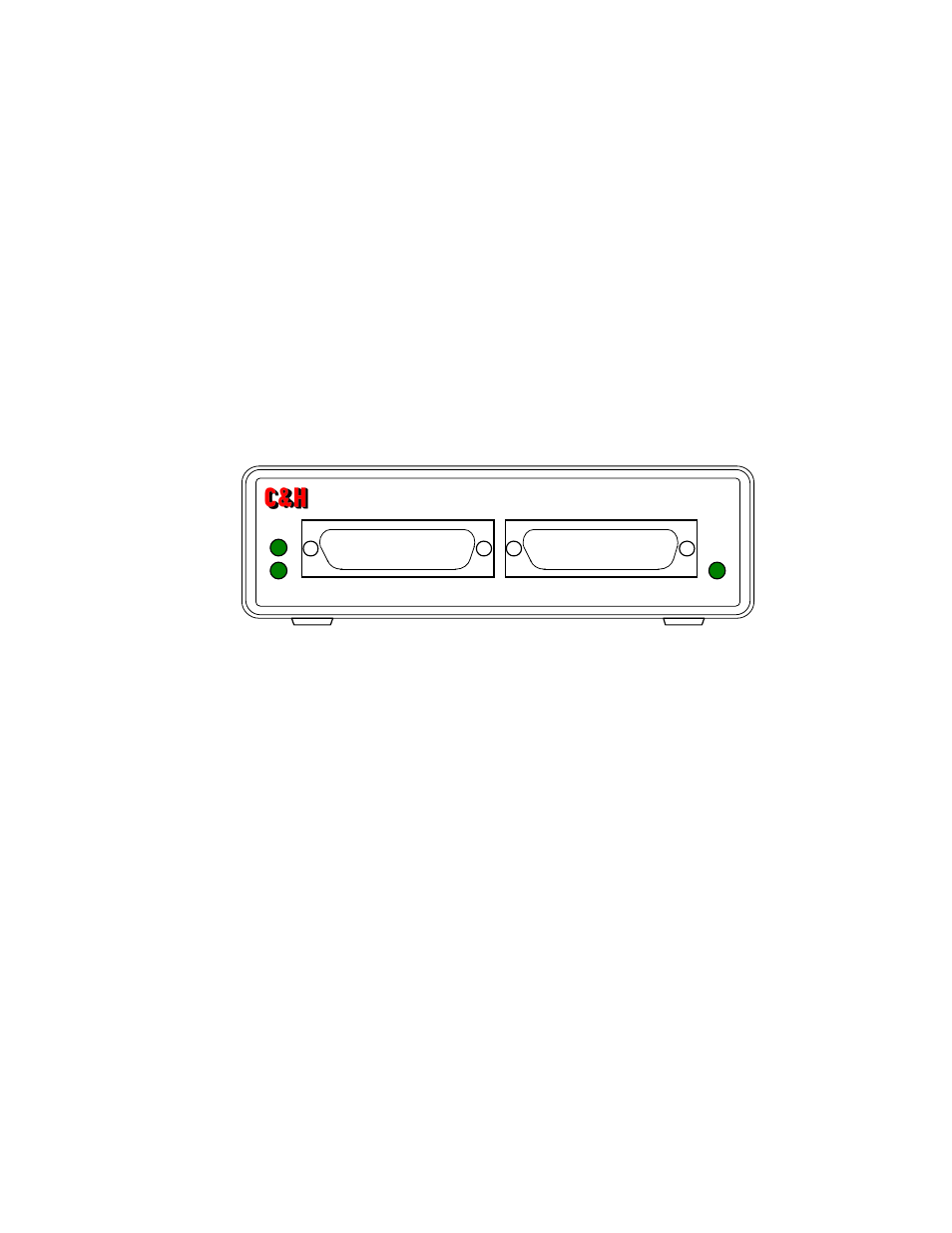
3.3 FRONT PANEL
The front panel of the EM405D contains two openings for access to the M-modules’ front panel
connections and three LED indicators as shown in Figure 6. As mandated by the M-module
specification, each M-module should provide a front panel connector containing the M-module
I/O signals. The two openings on the EM405D’s front panel provide access to these connectors.
The functions of the three front-panel LED indicators are:
PWR: indicates that power is supplied to the module and that the power switch is ON. The units
should be operating normally.
A, B: indicates that M-module A or B is currently being accessed. The LED will illuminate
temporarily each time the module is accessed by the host software.
Figure 6. Front Panel
B
A
EM405D ETHERNET M-MODULE CARRIER
PWR