CH Tech EM405D User Manual
Page 14
8
3.1.3 M-module Interface
The M-module interface provides the mechanism for the microcontroller to access the M-
modules. It is implemented using programmable logic that emulates a bridge between the
microcontroller and the M-module bus. The logic also provides trigger configuration and
control.
3.1.4 Power Conversion
The +12V input power is converted to the +3.3V power required by the carrier and the +5V,
+12V, and -12V power required by the M-modules. The input power can be supplied through
the 2.5mm power jack connector or through pins on the 9-pin DSUB connector.
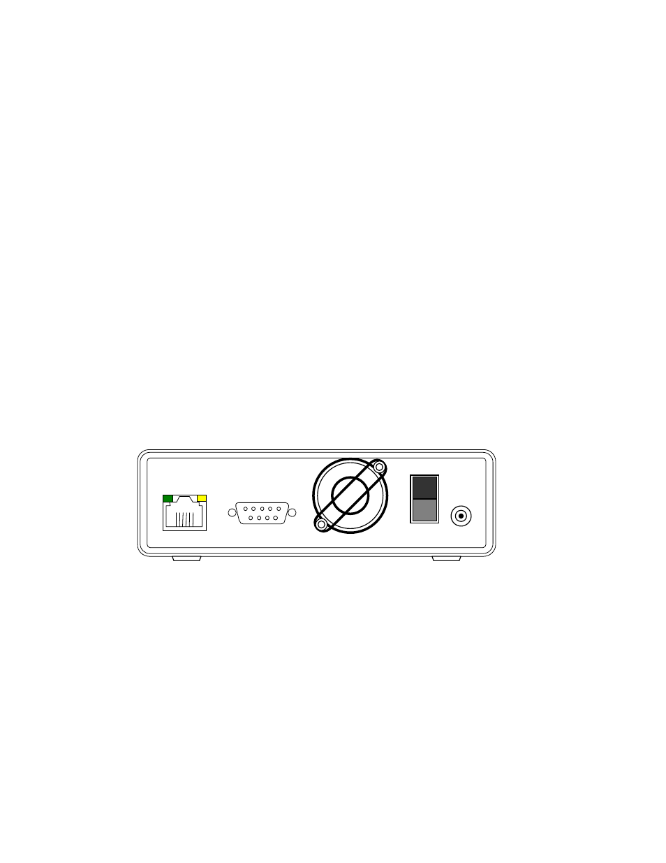
3.2 REAR PANEL
The rear panel of the EM405D contains a +12V power input connection, an Ethernet connection
or wireless antenna and a 9-pin DSUB connector that provides connection to M-module trigger
lines and an alternate power input connection. Also found on the rear panel are the fan and an
On/Off switch. Figure 5 shows the rear panel of the module. Refer to Appendix A for pin-out
details of the 9-pin DSUB connector.
Figure 5. Rear Panel
ETHERNET
10/100 BASE-T
+12VDC
IN
J1
POWER
ON
OFF