CH Tech EM405D User Manual
Page 13
7
3.0 FUNCTIONAL DESCRIPTION
3.1 GENERAL
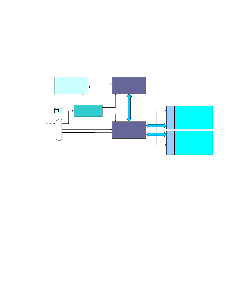
The EM405D provides a mechanical and electrical interface between an Ethernet bus and up to
two M-modules. It utilizes an embedded microcontroller to provide buffering and command
translation between the Ethernet interface and the M-modules. A simplified functional block
diagram is shown in Figure 4.
Figure 4. Functional Block Diagram
3.1.1 Embedded Controller
The embedded controller is implemented using a high-performance microcontroller. The
microcontroller executes system firmware that controls the translation between Ethernet and the
M-module interface. The system firmware implements a simple command protocol that allows
access to the M-modules I/O space, trigger mapping and carrier information and status. It also
provides data buffering and fan control.
3.1.2 Ethernet Interface
The Ethernet interface provides the physical and logical connection to the EM405D allowing
remote control of the M-modules. The EM405D is available with either wired 10/100 Base-T
Ethernet or wireless Ethernet (Wi-Fi). The interface supports the TPC/IP protocol for control of
the M-modules. It also supports DHCP, AutoIP, Telnet, HTTP and other standard protocols for
device configuration and management.
ETHERNET
MICRO
M-MODULE
INTERFACE
POWER
CONVERSION
PO
SI
T
ION
A
PO
SI
T
IO
N
B
+12VDC IN
M-MODULE A
M-MODULE B
TRIGGERS
OR
HERE
TRG IN
TRG OUT
10/100 BASE-T
OR WI-FI
9-PIN DSUB