Integrated network interface controller connector – Dell PowerEdge 7150 User Manual
Page 8
illustrates the USB connector and
defines the pin assignments and interface signals for the USB connector.
Figure B-7. Pin Numbers for the USB Connector
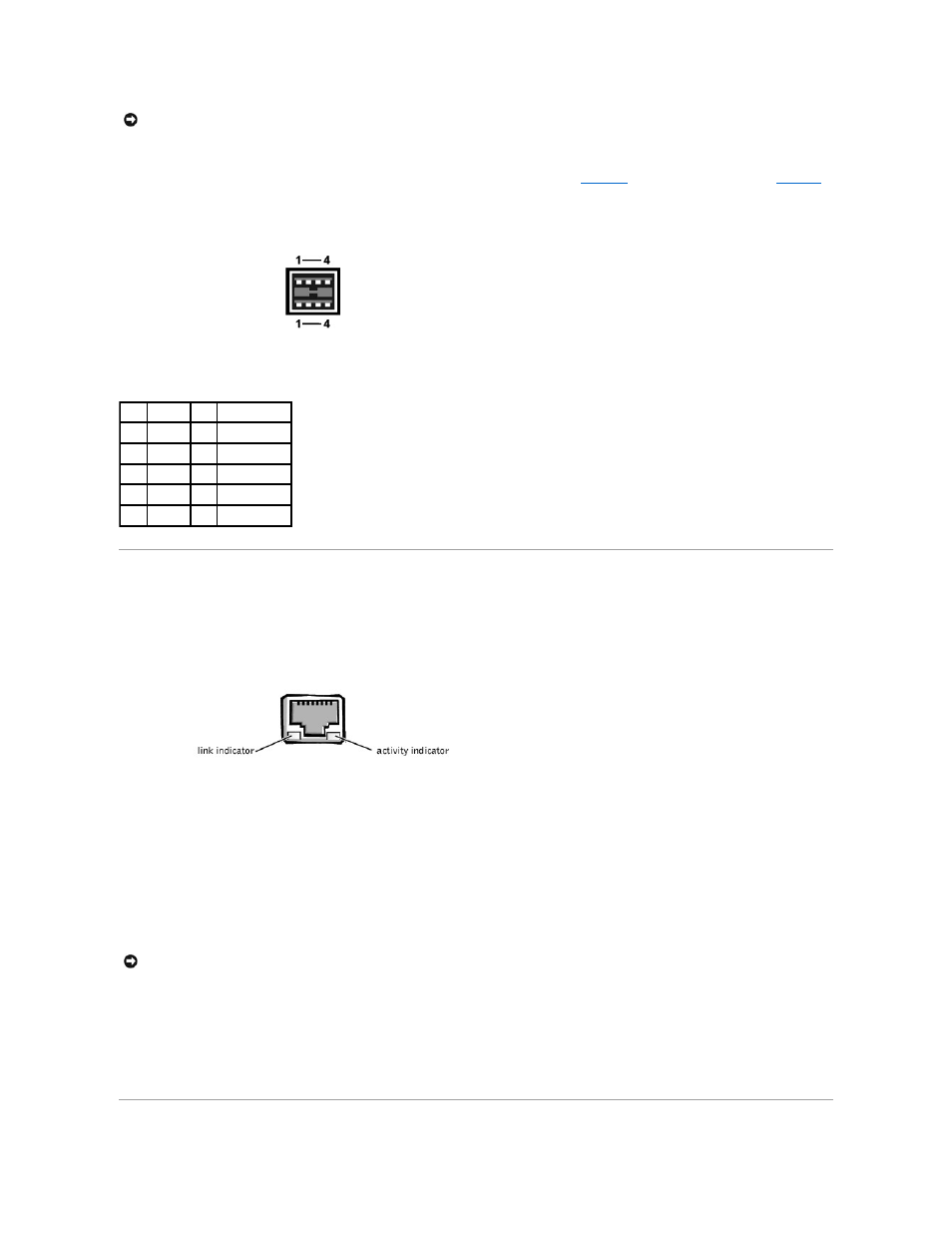
Integrated Network Interface Controller Connector
Your system has an integrated 10/100–Mbps NIC. The NIC provides all the functions of a separate network expansion card and supports both the 10BASE-T and
100BASE-TX Ethernet standards.
Figure B-8. NIC Connector
The NIC includes a Wake On LAN (WOL) feature that enables the computer to be started by a special LAN signal from a server management console. WOL
provides remote computer setup, software downloading and installation, file updates, and asset tracking after hours and on weekends when LAN traffic is typically at a
minimum.
Network Cable Requirements
Your computer's RJ45 NIC connector is designed for attaching an unshielded twisted pair (UTP) Ethernet cable equipped with standard RJ45-compatible plugs. Press
one end of the UTP cable into the NIC connector until the plug snaps securely into place. Connect the other end of the cable to an RJ45 jack wall plate or to an RJ45
port on a UTP concentrator or hub, depending on your network configuration. Observe the following cabling restrictions for 10BASE-T and 100BASE-TX networks.
l
For 10BASE-T networks, use Category 3 or greater wiring and connectors.
l
For 100BASE-TX networks, use Category 5 or greater wiring and connectors.
l
The maximum cable run length (from a workstation to a concentrator) is 328 ft(100 m).
l
For 10BASE-T networks, the maximum number of daisy-chained concentrators on one network segment is four.
NOTICE:
Do not attach a USB device or a combination of USB devices that draw a maximum current over 500 mA per channel or +5 V. Attaching devices
that exceed this threshold might cause the USB ports to shut down. See the documentation that accompanied the USB devices for their maximum current
ratings.
Table B-6. USB Connector Pin Assignments
Pin Signal
I/O Definition
1
Vcc
N/A Supply voltage
2
-DATA I/O Differential data
3
+DATA I/O Differential data
4
GND
N/A Signal ground
Shell N/A
N/A Chassis ground
NOTICE:
To avoid line interference, voice and data lines must be in separate sheaths.