Video connector, Usb connectors, Connector, and – Dell PowerEdge 7150 User Manual
Page 7: Table b-4
Video Connector
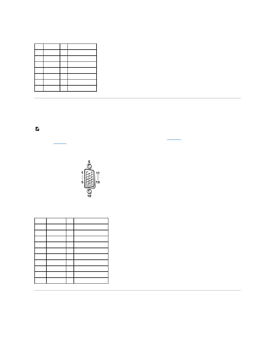
The system uses a 15-pin high-density D-subminiature connector on the back panel for attaching a video graphics array (VGA)-compatible monitor to your computer.
The video circuitry on the system board synchronizes the signals that drive the red, green, and blue electron guns in the monitor.
illustrates the pin numbers for the video
defines the pin assignments and interface signals for the video connector.
Figure B-6. Pin Numbers for the Video Connector
USB Connectors
Your system contains two USB connectors for attaching USB-compliant devices. USB devices are typically peripherals such as mice, printers, keyboards, and
computer speakers.
Table B-4. Mouse Connector Pin Assignments
Pin
Signal
I/O Definition
1
MCDATA I/O Mouse data
2
NC
N/A No connection
3
GND
N/A Signal ground
4
FVcc
N/A Fused supply voltage
5
MCCLK
I/O Mouse clock
6
NC
N/A No connection
Shell N/A
N/A Chassis ground
NOTE:
Installing a video card automatically disables the system's integrated video subsystem.
Table B-5. Video Connector Pin Assignments
Pin
Signal
I/O Definition
1
RED
O
Red video
2
GREEN
O
Green video
3
BLUE
O
Blue video
4
NC
N/A No connection
5–8, 10 GND
N/A Signal ground
9
VCC
N/A Vcc
11
NC
N/A No connection
12
DDC data out O
Monitor detect data
13
HSYNC
O
Horizontal synchronization
14
VSYNC
O
Vertical synchronization