I/o ports and connectors – Dell PowerEdge 7150 User Manual
Page 4
Back to Contents Page
I/O Ports and Connectors
Dell™ PowerEdge™ 7150 Systems User's Guide
Integrated Network Interface Controller Connector
This section provides specific information about the computer's I/O ports.
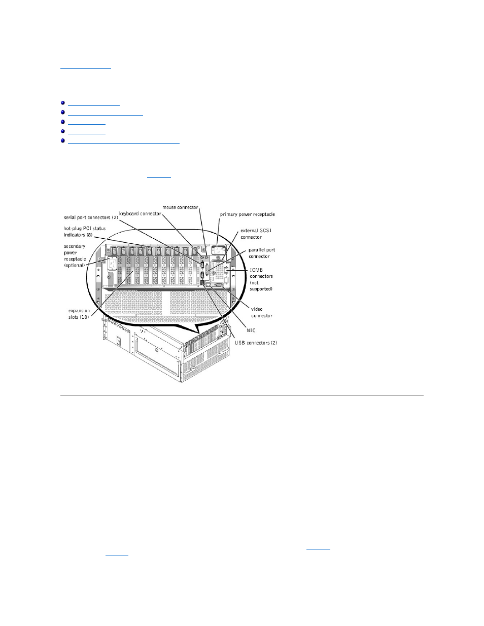
The I/O ports and connectors on the back panel of the computer are the gateways through which the computer system communicates with external devices, such as a
keyboard, mouse, printer, and monitor.
identifies the I/O ports and connectors for your system.
Figure B-1. Back-Panel Features
Serial and Parallel Ports
The two integrated serial ports use 9-pin D-subminiature connectors on the back panel. These ports support devices such as external modems, printers, plotters, and
mice that require serial data transmission (the transmission of data one bit at a time over one line).
Most software uses the term COM (for communications) plus a number to designate a serial port (for example, COM1 or COM2). The default designations of your
computer's integrated serial ports are COM1 and COM2.
The integrated parallel port uses a 25-pin D-subminiature connector on the computer's back panel. This I/O port sends data in parallel format (where eight data bits, or
one byte, are sent simultaneously over eight separate lines in a single cable). The parallel port is used primarily for printers.
Most software uses the term LPT (for line printer) plus a number to designate a parallel port (for example, LPT1). The default designation of the computer's integrated
parallel port is LPT1.
Port designations are used, for example, in software installation procedures that include a step in which you identify the port to which a printer is attached, thus telling
the software where to send its output. (An incorrect designation prevents the printer from printing or causes scrambled print.)
Serial Port Connectors
If you reconfigure your hardware, you may need pin number and signal information for the serial port connectors.
illustrates the pin numbers for the serial
defines the pin assignments and interface signals for the serial port connector.
Figure B-2. Pin Numbers for the Serial Port Connectors