System board led codes, Warning messages – Dell PowerEdge 1750 User Manual
Page 13
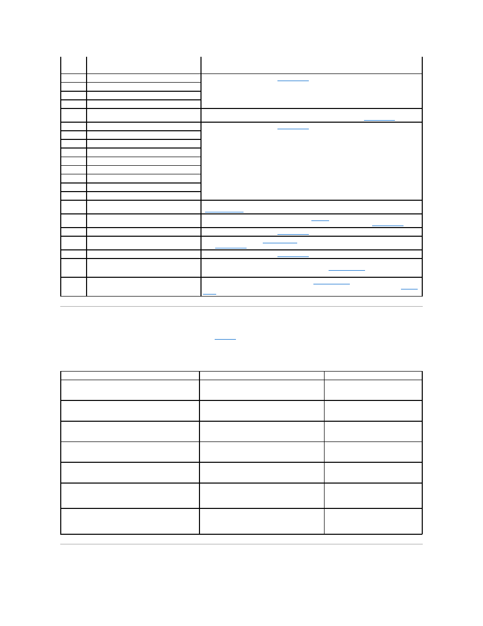
System Board LED Codes
The system board LEDs are visible only when the covers are open.
lists the system board LED codes and their meanings.
Table 3-7. System Board LED Codes
Warning Messages
2-1-1
through
2-4-4
Bit failure in the first 64 KB of main memory
3-1-1
Slave DMA-register failure
Replace the system board. See "
System Board
."
3-1-2
Master DMA-register failure
3-1-3
Master interrupt-mask register failure
3-1-4
Slave interrupt-mask register failure
3-2-4
Keyboard-controller test failure
Check the keyboard cable and connector for proper connection. If the problem persists, replace
the keyboard. If the problem persists, replace the system board. See "
System Board
."
3-3-1
CMOS failure
Replace the system board. See "
System Board
."
3-3-2
System configuration check failure
3-3-3
Keyboard controller not detected
3-3-4
Screen initialization failure
3-4-2
Screen-retrace test failure
3-4-3
Search for video ROM failure
4-2-1
No timer tick
4-2-2
Shutdown failure
4-2-3
Gate A20 failure
4-2-4
Unexpected interrupt in protected mode
Ensure that all expansion cards are properly seated, and then reboot the system. See
"
Expansion Cards
."
4-3-1
Improperly seated or faulty memory modules
Remove and reseat the memory modules. See "
Memory
." If the problem persists, replace the
memory modules. If the problem persists, replace the system board. See "
System Board
."
4-3-3
Defective system board
Replace the system board. See "
System Board
."
4-3-4
Time-of-day clock stopped
Replace the battery. See "
System Battery
." If the problem persists, replace the system board.
See "
System Board
."
4-4-1
Super I/O chip failure (defective system board)
Replace the system board. See "
System Board
."
4-4-3
Microprocessor frequency mismatch. Occurs
when the front-side (external) bus speed of a
microprocessor is not supported.
If video is available, a screen message identifies the faulty microprocessor. Replace the
microprocessor with a supported microprocessor. See "
Microprocessors
." If video is not
available, replace microprocessor 1 and then, if the problem persists, replace microprocessor 2.
4-4-4
Cache test failure (defective microprocessor)
Remove and reseat the microprocessor(s). See "
Microprocessors
." If the problem persists,
replace the microprocessor(s). If the problem persists, replace the system board. See "
System
Board
."
LED Indicator
Normal Operation
Error Condition
FANn_LED
(Located by each fan.)
Green
Blinking amber: A problem exists with the
associated fan.
THERMTRIP
(Located near the front left corner of the system board.)
Off
Amber: One or both of the processors
are overheated.
MISMATCH
(Located near the front left corner of the system board.)
Off
Amber: Processors do not match.
VRM1_OK
(Located near the edge of the system board by VRM1.)
Green
Off: Processor 1 VRM is disabled.
VRM2_OK
(Located near the edge of the system board by VRM2.)
Green if two processors are installed or off if only
one processor is installed.
Off if two processors are installed.
D_12V
(Located near the front left corner of the system board,
near the PS_PWR connector.)
Green
Off: System 12-V power is not available.
D_3VAUX
(Located near the front left corner of the system board,
near the PS_PWR connector.)
Green
System 3.3-V auxiliary power is not
available.