Figure 7-2, Figure 7-3 – Dell OptiPlex Gxi User Manual
Page 92
7-2
Dell OptiPlex GX
i
Midsize Systems Reference and Installation Guide
3.
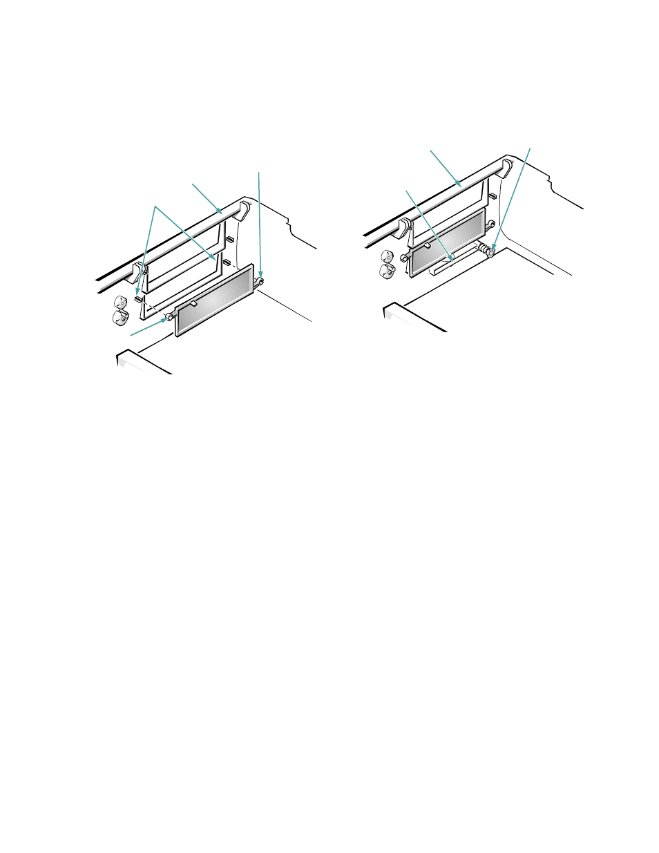
With your thumbs, press in each end of the insert
until it snaps free of the cover (see Figure 7-2).
Figure 7-2. Removing the Front-Panel Insert
for a 5.25-Inch Bay
To remove the insert covering the 3.5-inch bay,
follow
these steps:
1.
Complete steps 1 and 2 of the procedure for
removing a 5.25-inch insert.
2.
Inside the cover, locate the eject button mecha-
nism for the 3.5-inch bay. Press the mechanism
toward the front panel to snap the plastic insert
out of its opening (see Figure 7-3).
Figure 7-3. Removing the Front-Panel Insert
for the 3.5-Inch Bay
To replace a front-panel insert for a 5.25-inch bay,
work
from inside the cover. Position the insert behind the bay
opening, insert the two ring-tabs (one on each end of the
insert) over the posts on the inside of the opening, and
firmly press both ends of the insert into place (see Fig-
ure 7-2).
To replace the front-panel insert for the 3.5-inch bay,
work from outside the cover. Place the insert in position,
and press it into the opening.
ring-tab
posts
computer cover
(upside down)
ring-tab
3.5-inch front-
panel insert
computer cover
(upside down)
eject button
mechanism