Servicing the relief valve – Ames Fire & Waterworks 5001SS Reduced Pressure Detector Assemblies User Manual
Page 3
3
SERVICING THE RELIEF VALVE
RELIEF VALVE SERVICE INSTRUCTIONS
1. Prior to beginning any maintenance work, shut down the
water supply to the unit.
2. The relief valve is an integral part of the lid assembly and
may be serviced when the lid assembly is removed from
the body of the valve.
3. The relief valve may be disconnected from the sensing line
hose if desired to enable easier access to all parts of the
assembly.
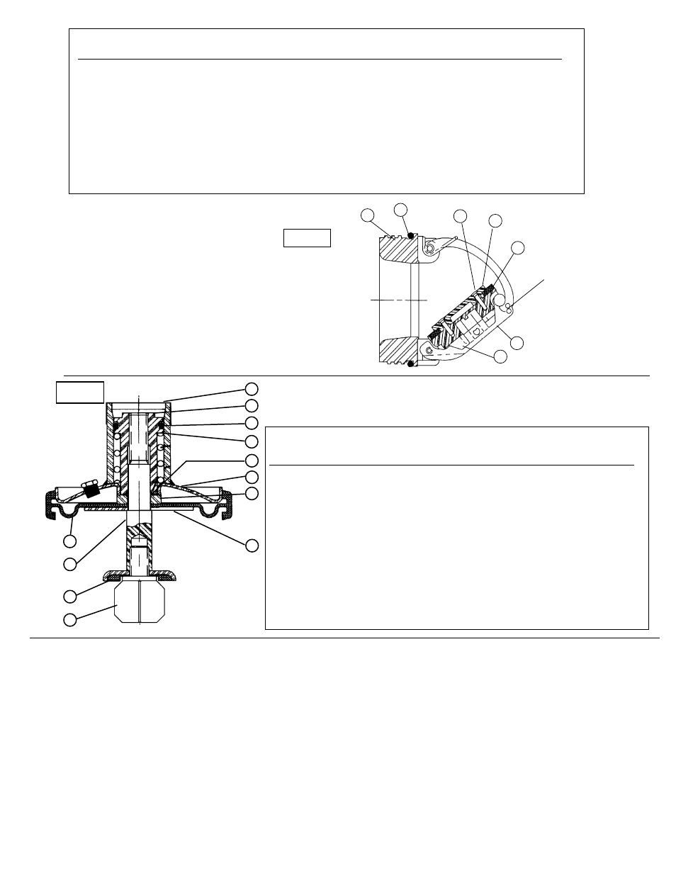
REPLACING THE SEALING DISC.
1. Unscrew the lower guide, (5) from the shaft (3).
2. Replace the sealing disc assembly (4).
3. Screw the lower guide (5) back into the shaft (3). The
lower guide will seal the assembly with pressure against
the elastomer in the sealing disc assembly (4).
COMPLETE DISASSEMBLY OF THE RELIEF VALVE.
1. Remove the sealing disc as above.
2. Remove the dust cover (10) from the cover weldment (1)
3. Unload the internal spring by unscrewing the guide,
shaft (9) using a socket wrench.
4. Draw the shaft out through the bottom of the diaphragm.
5. Remove the spring through the top of the cover weldment
6. Remove guide O-ring (6)
7. Remove O-ring (12) from the guide shaft.
REASSEMBLY
1. Replace all O-rings
2. Reverse disassembly steps above.
CAM-CHECK- PARTS TABLE #2
(Figure 8)
Item #
Part Description
Qty
3"
4"
6"
1.
Cover
1
116-04023
116-04023
116-06023
2.
Diaphragm/Gasket*
1
16-00067
16-00067
16-00075
3.
Shaft
1
16-00063
16-00063
16-00073
4.
Sealing Disc*
1
16-00054
16-00054
16-00054
5.
Guide, Lower
1
16-00055
16-00055
16-00055
6.
O-Ring*
1
5-06090
15-06090
5-06090
7.
Support Disc
1
16-00059
16-00059
16-00072
8.
Disc, Diaphragm Stop
1
16-00058
16-00058
16-00074
9.
Guide, Upper
1
16-00061
16-00061
16-00061
10.
Cover, Dust
1
980-00721
980-00721
980-00721
11.
O-Ring, Upper*
1
5-06089
5-06089
5-06089
12.
Spring
1
16-00099
16-00099
16-00066
13.
Relief Valve Rubber Kit
1
116-04031
116-04031
116-06031
(consists of * items)
PARTS TABLE #3
(Figure 9)
Item #
Part Description
Qty.
3”
4”
6”
1.
1st Cam-Check O-ring (removable)*
1
6-05064
6-05064
6-05142
2.
Clapper Assembly (removable)
1
116-04026
116-04026
116-06026
3.
Clapper Retaining Plate Screws (removable)
4
16-00080
16-00080
16-00084
4.
Clapper Retainer Plate (removable)
1
16-00017
16-00017
16-00018
5.
Clapper Disc (removable)*
1
16-00019
16-00019
16-00020
6.
Pivot Arm Pin (removable) 2 c-clips*
1
16-00041
16-00041
16-00025
7.
2nd Cam-Check O-ring (removable)*
1
6-05021
6-05021
6-05121
8.
1st Cam-Check Rubber Kit
1
116-04032
116-04032
116-06032
(consists of * items)
9.
2nd Cam-Check Rubber Kit
1
116-04033
116-04033
116-06032
(Consists of * items)
10.
C-Clips Kit
1
116-04034
116--04034
116-06033
Note: Align holes
and insert pin or
small screwdriver
to hold in open
position.
Figure 8
5
4
3
1
7
6
2
Figure 9
8
10
9
11
12
7
6
1
2
3
4
5