Cam-check disassembly – Ames Fire & Waterworks 5001SS Reduced Pressure Detector Assemblies User Manual
Page 2
2
Item # Part Description
Qty
3"
4"
6"
1.
#1 Cam-Check
1
116-04200
116-04200
116-06200
2.
#2 Cam-Check
1
116-04101
116-04101
116-06101
3.
Relief Valve Assembly
1
116-04020
116-04020
116-06020
Cover Plate
Diaphragm
Relief Valve Internals
4.
Groove Coupler
1
6-05028
6-05028
6-05128
5.
Diaphram / Gasket
1
16-00067
16-00067
16-00075
6.
Ball Valve
3
980-00527
980-00527
980-00449
7.
Relief Valve Seat Assy.
1
116-04022
116-04022
116-04022
8.
Relief Valve Sensing Line
1
16-00079
16-00079
16-06079
9.
1st Cam Check O-ring
1
6-05064
6-05064
6-05142
10.
2nd Cam Check O-ring
1
6-05021
6-05021
6-05121
11.
Shutoff valves
(not shown)
DETAILED PARTS LISTING - PARTS TABLE #1
(Figure 7)
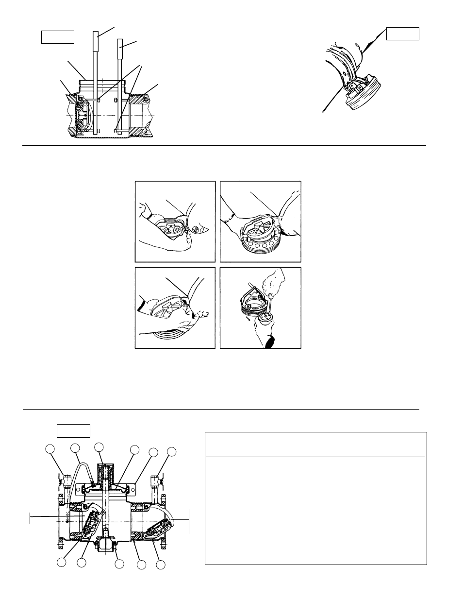
Figure 1
Long Cam
Arm
3", 4" & 6" RP 1st
Cam-Check
CAM-CHECK DISASSEMBLY
Please use caution when disassembling cam-check.
The cam-check is a spring-loaded mechanical device. Failure to do so may result in potential injury.
FIGURE 5
Remove 1 c-clip from the center
pivot pin. Withdraw the center
pivot pin from the clapper and
the hinge arms. Remove the
clapper assembly from the
check assembly module. Note:
You may replace this item as
an assembly or you may
continue and replace only the
sealing disc.
FIGURE 4
Using your free hand, swing the
clapper assembly away from
the seat. Align (A) lockout
holes.
FIGURE 3
Press down on the check
assembly to unload the
cambar from hinge arms and
roller. Then place a thin rod
into a maintenance hole in one
hinge arm.
FIGURE 6
Disassemble the clapper by
removing 4 screws, disc retainer
and the clapper disc. Disc may
be flipped if sealing surface is
damaged.
Before reinstallation of check assembly, thoroughly clean O-ring groove and lubricate O-ring
with F.D.A. approved lubricant.
5001SS: Contact factory for bypass component servicing information.
Air Gap Drain: Contact factory for additional information.
Short Cam
Arm
6
8
3
5
4
6
2
10
7
9
1
#1 Cam-
Check
#2 Cam-
Check
SCREWDRIVER OR PRYBAR
SCREWDRIVER OR PRYBAR
COVER BOLTS
CAM CHECK
BODY
CAM CHECK
Figure 2
Figure 7