Maintenance instructions, Disassembling the relief valve, Replacing the diaphragm – Ames Fire & Waterworks 400B Bronze Reduced Pressure Zone Assemblies User Manual
Page 4: Replacing the relief valve disc and seat, Reassembling the relief valve
4
WARNING
!
Depressurize valve before servicing.
No special tools are required to service the Series 400B
1
⁄
4
" – 2"
(8 – 50mm).
Before servicing, make sure the water is turned off or shutoff valves
are closed.
The following procedures provide information for replacing the
diaphragm, the relief valve disc, and the relief valve seat. It is
recommended that you visually inspect these parts to determine if a
replacement or a cleaning is required.
Disassembling the Relief Valve
1. Remove the relief valve cover bolts while holding the cover down.
2. Turn the cover counterclockwise for 1⁄4 turn, and lift it straight off
while still applying pressure to the cover with your hand.
WARNING
!
Make sure you apply pressure to the cover as you lift it straight off.
Due to the release of pressure when removing the cover, the relief
valve spring may eject quickly.
3. Remove the relief valve assembly (includes cover O-ring, stem
and diaphragm assembly).
4. Remove the relief valve spring.
5. Remove the pressed in relief valve seat and seat O-ring.
Replacing the Diaphragm
6. Using a wrench, loosen the diaphragm assembly by turning
the hex bolt counterclockwise.
7. Remove the diaphragm and replace with a new diaphragm
if required, or clean the existing diaphragm. The molded step
of the diaphragm should point down toward the relief valve
stem.
8. Using a wrench, reassemble the diaphragm assembly
by turning the hex bolt clockwise to tighten.
Replacing the Relief Valve Disc and Seat
9. Using a phillips screwdriver, remove the screw in the relief valve
disc and replace the disc if required, or clean the existing disc.
10. Place the screw back into the relief valve disc and tighten.
11. Replace the relief valve seat with a new seat if required, or
clean the existing seat.
Reassembling the Relief Valve
12. Place the relief valve seat back into the chamber bore.
13. Slide the diaphragm assembly into the relief valve seat.
14. Place the spring onto the diaphragm assembly.
15. Place the cover O-ring on the diaphragm assembly.
16. Line up the grooves on the relief valve cover with the grooves
in the relief valve body and turn the cover clockwise 1⁄4 turn to
seat the cover.
17. Using a wrench, place the bolts back into the cover and tighten.
CAUTION
!
If the cover does not lie flat against the relief valve body, the
diaphragm assembly is not installed properly and damage can
result. Remove the bolts and cover, realign the diaphragm
assembly, and place the cover back on the relief valve body.
18. Open the shutoff valves.
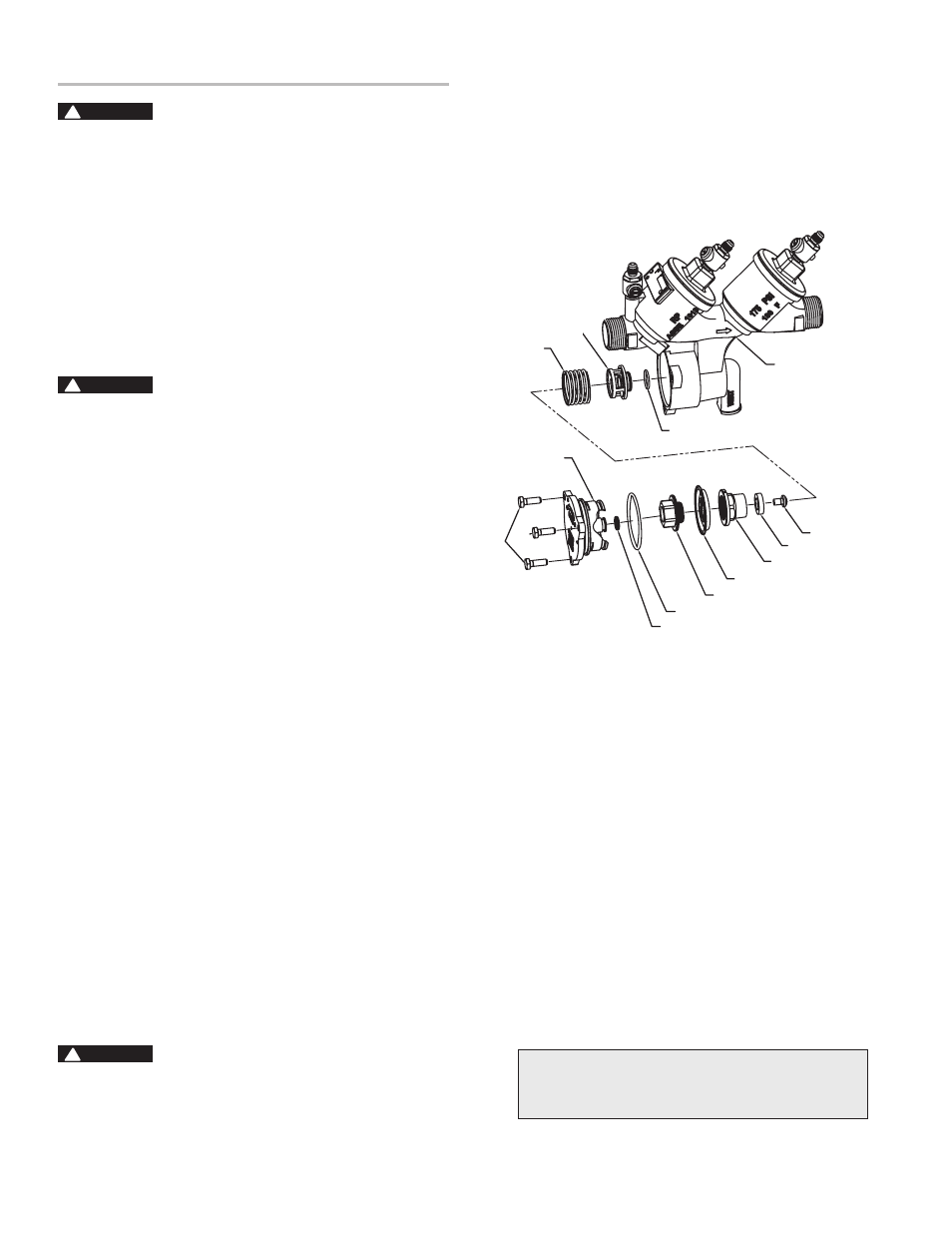
Maintenance Instructions
Quad-Ring
Relief Valve cover O-ring
Diaphragm nut
Relief Valve Diaphragm
Relief Valve Stem
Relief Valve Disc
Relief Valve
Disc Screw
Relief Valve Seat
Body
Relief Seat O-ring
Relief Valve
Spring
Relief
Valve
cover
cover
Bolts
For repair kits and parts, refer to our Backflow Pre-
vention Products Repair Kits & Service Parts price list
PL-A-RP-BPD found on
www.amesfirewater.com.