Cabinet construction – FRIGIDAIRE FPDS3085PF User Manual
Page 8
8
30" DUAL FUEL SLIDE-IN RANGE INSTALLATION INSTRUCTIONS
(Models with an Electric Oven and a Gas Cooktop)
Direct Electrical Connection to the Circuit
Breaker, Fuse Box or Junction Box
If the appliance is connected directly to the circuit
breaker, fuse box or junction box, use flexible, armored
or nonmetallic sheathed copper cable (with grounding
wire). Supply a U.L. listed strain-relief at each end of
the cable. At the appliance end, the cable goes through
the Direct Connection Hole (see Figure 5) on the
Cord Mounting Plate. Wire sizes
(copper wire only)
and connections must conform to the rating of the
appliance. A 50A time-delay fuse or circuit breaker is
recommended (minimum 40A).
Where local codes permit connecting the
appliance-grounding conductor to the neutral
(white) wire (see Figure 5):
1. Be sure that no power is supplied on the cable from
residence.
2. Remove the grounding strap from the terminal block
and from the appliance frame.
3. In the circuit breaker, fuse box or junction box:
a) Connect the green (or bare copper) wire, the
white appliance cable wire, and the neutral (white)
wire together.
b) Connect the 2 black wires together.
c) Connect the 2 red wires together.
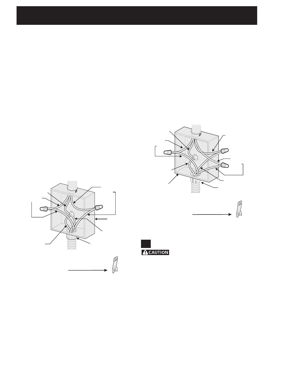
Figure 5
3-Wire (Grounded Neutral) Electrical System
(Example: Junction Box)
Cable from Residence
Junction
Box
White Wire
U.L.-listed Conduit
Connector (or CSA
listed)
Cable from
Appliance
Green
(or Bare Copper)
Wire
Red
Wires
Neutral
(white) Wire
Black
Wires
NOTE: Be sure to remove the
supplied grounding strap.
Where local codes DO NOT permit connecting
the appliance-grounding conductor to the neutral
(white) wire, or if connecting to 4-wire electrical
system (see Figure 6):
1. Be sure that no power is supplied on the cable
from residence.
2. Remove the grounding strap from the terminal
block and from the appliance frame.
3. In the circuit breaker, fuse box or junction box:
a) Connect the white appliance cable wire to the
neutral (white) wire.
b) Connect the 2 black wires together.
c) Connect the 2 red wires together.
d) Connect the green (or bare copper) grounding
wire to the grounding wire of the circuit breaker,
fuse box or junction box.
NOTE: Be sure to remove the
supplied grounding strap.
U.L.-listed Conduit
Connector (or CSA
listed)
Figure 6 – 4-Wire Electrical System
(Example: Junction Box)
Cable from Residence
Black
Wires
Junction
Box
White Wire
Cable from
Appliance
Green (or Bare
Copper) Wire
Red
Wires
White Wire
Green (or Bare
Copper) Wire
5
Cabinet Construction
To eliminate the risk of burns or fire
by reaching over heated surface units, do not have
cabinet storage space above the range. If there is
cabinet storage space above range, reduce risk by
installing a range hood that projects horizontally a
minimum of 5" (12,7 cm) beyond the bottom of the
cabinet.
Countertop Preparation
• The cooktop sides of the range fit over the cutout
edge of your countertop.
• If you have a
square finish (flat) countertop, no
countertop preparation is required. Cooktop sides lay
directly on edge of countertop.
• Formed front-edged countertops must have
molded edge shaved flat 3/4" (1,9 cm) from each
front corner of opening (Figure 7).