0 hardware configuration, 1 connector alignment, 2 connector wiring – Cooper Instruments & Systems MasterLink 3000 Wireless Load Cell Amplifier User Manual
Page 7
CF 187
5
RevA
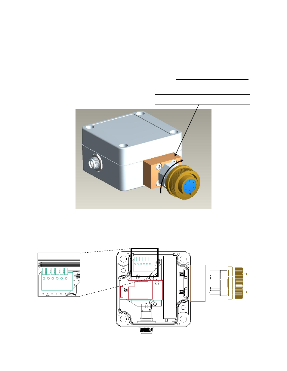
4.0 HARDWARE CONFIGURATION
4.1 Connector Alignment
As the MasterLink 3000 has been developed to provide a compact integration to connectorized strain gage
transducers, the connector has the ability to rotate to a desired orientation for the application. The connector
adapter is a pipe thread which screws into the connector plate block. To maintain the IP rating of the system, the
connector must always be tightened into the block and not loosened. In order to tighten the connector, a wrench
must used both on the connector plate block and the connector adapter. If for some reason the connector
needs to be removed, the threads must be cleaned and a new layer of teflon tape must be used.
4.2 Connector Wiring
Pinout:
1
Battery + (RED)
2
Battery - (BLACK)
3
-Excitation
4
-Signal
5
+Signal
6
+Excitation
CONNECTOR PLATE BLOCK
6 5 4 3 2 1