Load sensing setup – Great Plains CTA4000 HD Operator Manual User Manual
Page 29
Great Plains Manufacturing, Inc.
Preparation and Setup
25
2012-11-28
160-037M
Load Sensing Setup
To operate the CTA4000HD, some tractors with
load-sensing or constant-flow hydraulics need a bypass
valve. See “Hydraulic Bypass Kit” on page 59 for
ordering information. Contact your Great Plains dealer to
order the valve.
Machine Damage Risk:
Failure to install the bypass valve may cause major tractor
damage. Contact your tractor dealer to verify if the bypass
valve is needed.
Refer to Figure 25
1.
After installing the bypass valve
, adjust as follows:
2.
Loosen lock-ring
and completely close off bypass
cross-flow by turning knob
fully clockwise.
Refer to Figure 26
3.
Set valve levers for Field operation.
4.
On tractor, adjust circuit flow-control valve so
openers raise and lower at a reasonable speed.
Note: The faster openers raise and lower, the greater
potential for oil heating, premature wear or tractor
damage.
5.
Engage tractor hydraulics for fan and
opener-lift-and-fold circuits. Lock hydraulic levers for
continuous oil flow. Make sure cart fan is operating at
normal speed (about 3600 rpm).
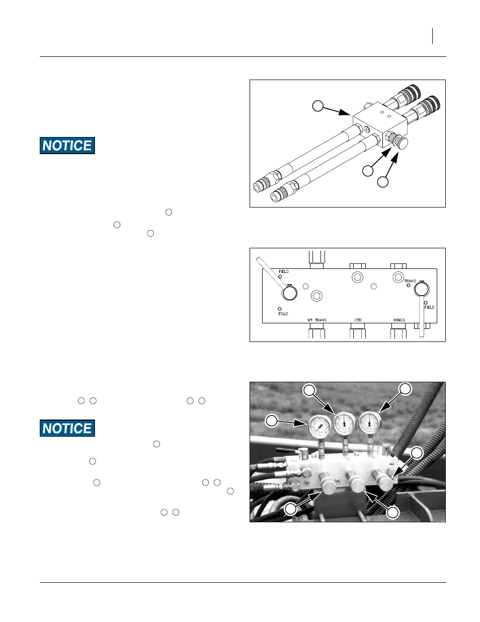
Refer to Figure 27 and Figure 25
6.
Adjust wing and center down-pressure-control
valves
,
on implement so gauges
,
read
1500 psi.
Do not adjust weight-transfer valve
at this time.
To avoid implement damage, never set weight-transfer valve
above 1000 psi
.
7.
While watching opener gauges, slowly adjust bypass
valve knob
just until needles on gauges
,
move down from 1500 psi. Lock bypass valve ring
at this setting.
8.
Adjust pressure-control valves
,
to desired
opener down pressure. See “Sub-Frame
Down-Force” on page 43.
Figure 25
Optional Bypass Valve
17987
3
2
1
1
2
3
Figure 26
Levers for Bypass Setup
26372
Figure 27
Pre-Adjusting for Bypass
26457
8
5
6
7
4
9
4
5
6
7
8
9
3
6
7
2
4
5