Warning, Maintenance – Great Plains PT8030 V1015 Operator Manual User Manual
Page 39
37
Section 5 Maintenance and Lubrication
4/12/05
PT6030 and PT8030 Pull-Type Planter 401-032M-B
Great Plains Mfg., Inc.
Section 5
Maintenance and Lubrication
Maintenance
Proper servicing and maintenance is the key to long imple-
ment life. With careful and systematic inspection, you can
avoid costly maintenance, downtime and repair.
Always turn off and remove the tractor key before making
any adjustments or performing any maintenance.
!
WARNING!
You may be severely injured or killed by being crushed under a
falling planter. Always install cylinder stops before working on
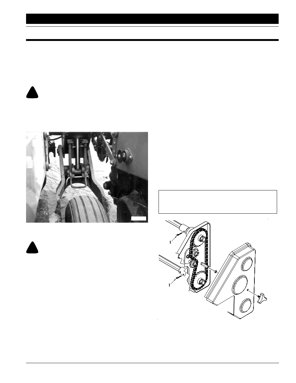
planter. To install the stops, refer to Figure 5-1. Raise planter to
transport position. Pivot cylinder stop into position on wheel
module cylinder rods. Lower planter onto stop. Install bent pin
and secure with cotter pin.
16889
Figure 5-1
Cylinder Stop
!
WARNING!
Escaping fluid under pressure can have sufficient pressure to
penetrate the skin. Check all hydraulic lines and fittings before
applying pressure. Fluid escaping from a very small hole can be
almost invisible. Use paper or cardboard, not body parts, and
wear heavy gloves to check for suspected leaks. If injured, seek
medical assistance from a doctor that is familiar with this type
of injury. Foreign fluids in the tissue must be surgically removed
within a few hours or gangrene will result.
1.
Inspect hoppers for debris and clean if necessary.
2.
Clean dirt and grease from chains and moving parts.
3.
Lubricate planter at points listed under Lubrication,
page 44.
4.
Torque all bolts, screws and nuts to the correct values
listed on Torque Values Chart, “Appendix,” page 55.
Check latches and other fasteners on the planter to
prevent failures in the field.
5.
Check all bolts and replace worn parts on the planter.
Check that all safety decals and reflectors are legible.
Replace if damaged. Refer to Safety Decals, “Impor-
tant Safety Information,” page 5.
Replacing Shear Pins
Refer to Figure 5-2.
The cotter pins (1) that connect the shafts to the transmis-
sion will shear when an excessive load is put on the shafts.
Infrequent or improper lubrication causes binding of mov-
ing parts within the planter. This binding will cause the cot-
ter pins to shear, thus preventing breakage of planter
parts.
Check for binding by turning the drive shaft with all seed
hoppers installed and seed meters engaged. If the drive
shaft is hard to turn, disengage one seed-meter clutch at a
time to find the problem clutch.
Improper shaft alignment can also cause pins to shear.
Refer to Shaft Alignment, page 38, to check shaft align-
ment.
When the drill shaft can be turned freely by hand, replace
the cotter pin.
IMPORTANT: Replace cotter pins with cotter pins of
the same size. Do not replace with other type pins.
16862
Figure 5-2
Transmission Cotter Pins & Shear Pins