Hydraulic assembly – Great Plains 4336 DH Predelivery Manual User Manual
Page 19
Great Plains Manufacturing, Inc.
Assembly
15
05/22/2012
556-100Q
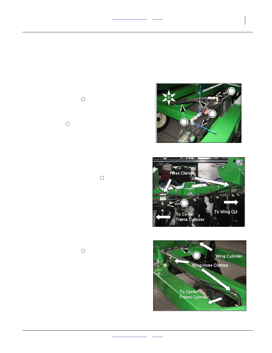
Hydraulic Assembly
Note: The brackets and hose clamps for mounting the hoses
to the scrapers are in a box shipped with the unit. See
hydraulic layouts in “Operators Manual” for complete
hose routings. When connecting these hoses, route the
hoses through the machine, as shown in the following
pictures
Refer to Figure 11
41. Connect the hoses from the center section to the wing, lift
cylinders. The hose and the fitting that are to be con-
nected have a colored tie
to assist in connecting the
proper hose to the proper fitting. (To double check this
hose routing, make sure the hose connected to the rod
end of the main lift cylinder on the center-frame, connects
to the base end of the cylinder on the wing.) Connect the
hose to the fitting
that does not have the colored ties.
Refer to Figure 12
42. Route the hoses along scraper bar tubes as shown.
Secure with hose clamps. Be sure to allow some extra
hose at the hinge line to allow for flexing during folding.
Mount hose holder scraper bracket
to scraper tube
with 1/2 x 2 1/32 x 3 1/4 u-bolts and 1/2 flange nut.
Refer to Figure 13
Route hoses along wing frames as shown. Fasten hoses with
hose clamps and hose wraps
as needed.
Figure 11
Hose Color Ties
42140
2
U
D
F
B
L
R
1
4
1
2
Figure 12
Scraper Bar Hose Routing
42141
3
3
Figure 13
Wing Hose Routing
42143
4
4