Narrow hitch and lever link assembly – Great Plains 4336 DH Predelivery Manual User Manual
Page 15
Great Plains Manufacturing, Inc.
Assembly
11
05/22/2012
556-100Q
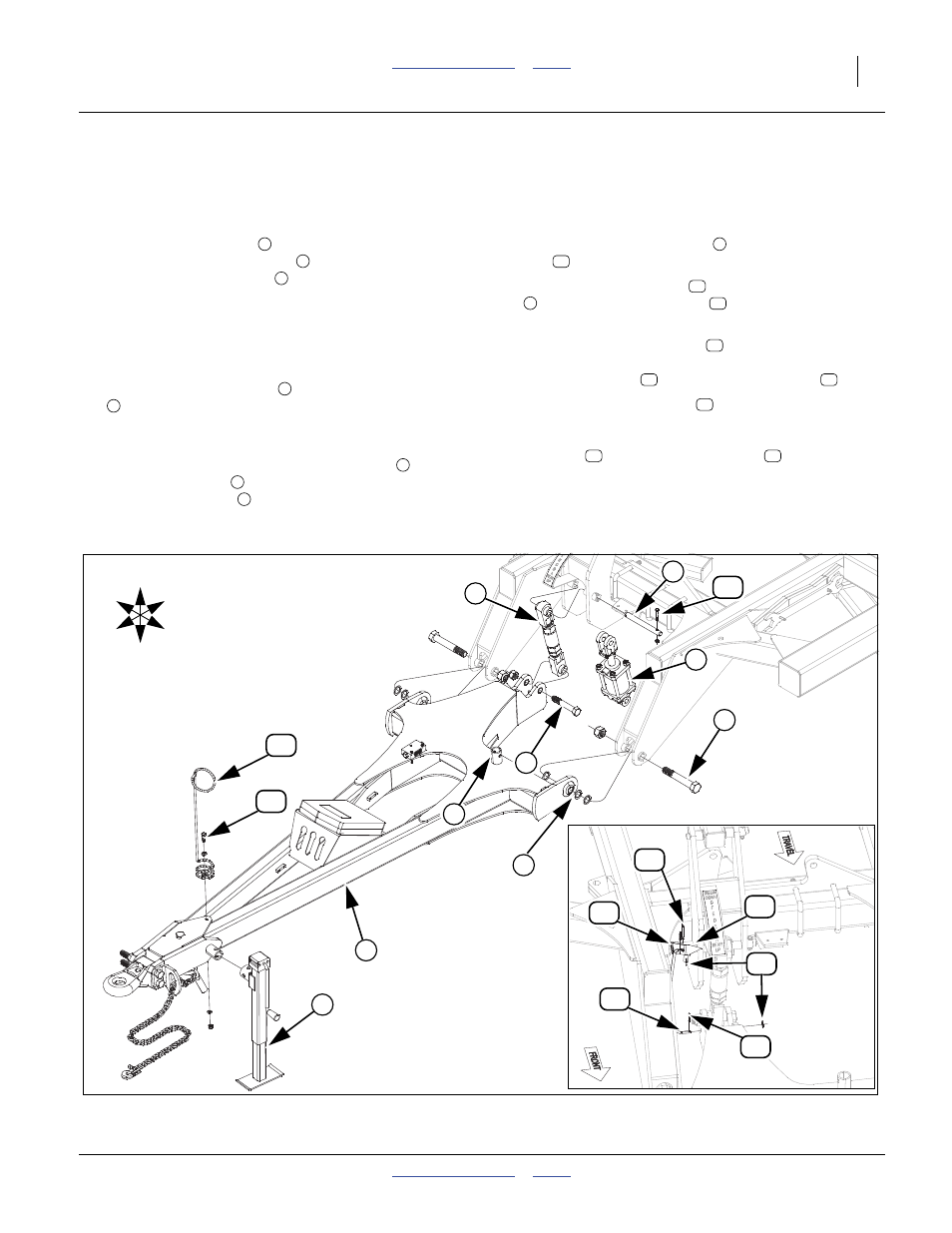
Narrow Hitch and Lever Link Assembly
Note: For 4330-4336 models, skip to, See “Wide Cen-
ter Hitch and Cylinder Assembly” on page 12.
Refer to Figure 8
16. Install hitch assembly
to front of center frame with
the 1 1/4 x 8 Gr. 8 hex bolts
provided. Be sure and
install 1 1/4 flat washers
as needed on both sides,
to insure a tight fit (be sure and have same amount
on both sides of hitch). Secure with the 1 1/4 top lock
nuts. Bolts need to be tightened down securely on
the ball joints but do not torque as hitch needs to
pivot freely.
17. Remove the tongue jack
from its storage location
at rear of hitch and install it on the jack stub at the
front of the hitch frame to support the front side of
hitch.
18. Connect the bottom of leveling turnbuckle
or
hydraulic cylinder
to rear of hitch with 1 x 6 Gr. 8
special thread bolt
, and 1 nylon lock nut, (do not
torque bolt), top to middle hole of leveler assembly
with the 1 x 9 1/2 hinge pin
, 3/8 x 2 1/4 Gr. 8 hex
bolt
and 3/8 top lock nut.
19. Attach spring hose loop
to front of hitch assembly
with 1/2 x 1 1/2 hex bolt
, 1/2 flat washer, 1/2
lock washer and 1/2 nut.
20. Attach level gauge pointer
over tube on right side
of leveler assembly, secure with 2.25 x 1.50 x 10ga
machine washer
and 3/16 x 2 cotter pin
.
21. Connect level gauge link
, bottom side with extra
bend through hole in back of hitch, top side through
hole in level gauge pointer. Secure with 3/8 flat
washers
and 1/8 x 1 cotter pins
.
22. Bolts may be tightened to specs, See “Torque Val-
1
2
3
4
5
6
7
8
9
10
11
1
12
13
14
15
16
17
18
2
Figure 8
Narrow Hitch & Leveler Link
42136
42130
4
3
9
6
1
U
D
F
B
L
R
5
8
16
14
18
13
17
15
7
10
11
12