3329-4336 wing assembly – Great Plains 4336 DH Predelivery Manual User Manual
Page 18
14
3323-4336DH
Great Plains Manufacturing, Inc.
556-100Q
05/22/2012
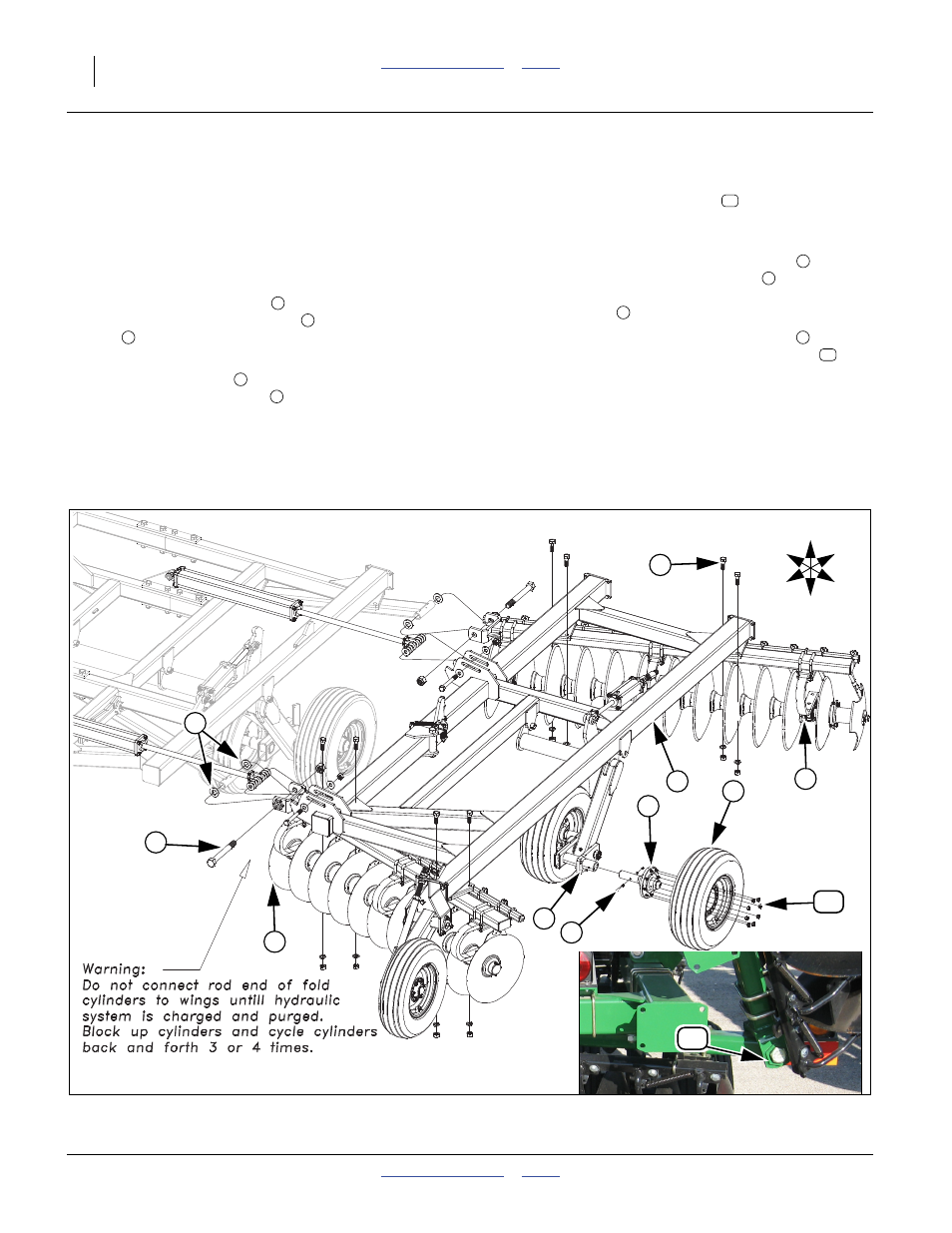
3329-4336 Wing Assembly
Note: The wing assembly will be the same on both the
narrow and wide center except the wing hinge will
be opposite on narrow center. Wide center shown.
Bolts must be installed so the head of the bolt is in the
bolt stop as shown in inset picture
.
Refer to Figure 10
34. With the center frame stands removed, the center
frame gangs should be resting on the floor.
35. Connect the wing gangs
to the center gang bars
using the 1 1/2 x 13 hex bolts
, two 1 1/2 flat wash-
ers
(one on each side) and 1 1/2 nylon lock nut.
Snug bolts but do not torque as wing must pivot.
36. Set the wing frame
on the gang bars and attach
with 1 x 3 Gr. 8 hex bolts
, 1 lock washers and 1
nuts.
Note: Do not hook up rod end of fold cylinder until sys-
tem purged of air. See “Purging Hydraulic Sys-
tem” on page 18.
37. Bolt the 8-bolt hub and spindle assembly
(if not
installed), to the wing walking beam
(tab or notch
needs to be assembled towards top) with 5/16 x 4
Gr. 8 hex bolts
and 5/16 top lock nut.
38. Mount the 8-bolt tire and wheel assembly
onto the
hubs (valve stem outward) with 5/8” lug nuts
.
39. Tighten all bolts to specs, See “Torque Values
40. Repeat the same procedure for the other wing.
11
1
2
3
4
5
6
7
8
9
10
U
D
F
B
L
R
Figure 10
3329-4336 Wing
41615
42138
1
3
4
6
1
5
7
9
8
10
2
11