Frame height, Single gauge wheel, Dual gauge wheels – Great Plains 2025P Operator Manual User Manual
Page 39
8/14/2006
118-928M
37
Adjustments
Frame Height
Drill operating height directly affects the working
range of the drill openers. Initially adjust frame
height as explained under “Leveling Drill”, page 17.
You can make further adjustments to compensate
for field conditions.
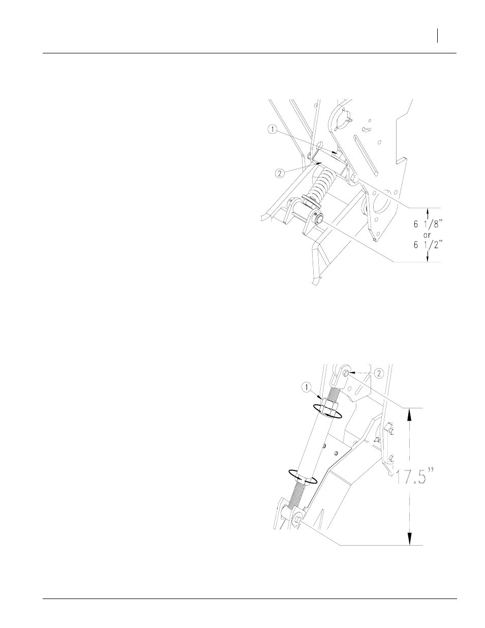
Single Gauge Wheel
Refer to Figure 45
1.
Make sure block mount of the spring linkage (2)
is in the lower mount hole for planting in bedded
irrigation. The upper hole is for non-bedded
ground.
2.
Set spring linkage length. Turn spring linkage to
shorten or lengthen as necessary. Initially set
length to 6 1/2 inches between pin centers to
achieve a 26-inch frame height for 25 series
openers and 6 1/8 inches to achieve a 24-inch
frame height for 20 series openers. When ad-
justing the linkage length, remember:
• Lengthening linkage raises drill.
• Shortening linkage lowers drill.
Level drill with top three-point link.
NOTE: Lowering the drill increases the risk of
opener damage on rocks or obstructions.
Dual Gauge Wheels
Refer to Figure 46
1.
Loosen jam nut near top clevis of each gauge-
wheel turnbuckle.
NOTE: Jam nut is left-hand threaded.
2.
Make sure upper clevis (2) is in upper mount
hole as shown for 20 series and in the lower
mount hole for HD 10 series.
3.
Set turnbuckle length. Turn turnbuckle to short-
en or lengthen as necessary. Initially set length
to 17 1/2 inches between pin centers to achieve
a 24-inch dimension for 20 series openers and
26-inch dimension for HD 10 series openers.
When adjusting the turnbuckle length, remem-
ber:
• Lengthening turnbuckle raises drill.
• Shortening turnbuckle lowers drill.
4.
After adjusting both turnbuckles to the same
length, tighten jam nuts.
5.
Level drill with top three-point link.
NOTE: Lowering the drill increases the risk of
opener damage on rocks or obstructions.
Figure 45
Single Gauge Wheel Linkage
Figure 46
Dual Gauge Wheel Turnbuckle
22845
22848