Capacitance, Thermal resistance, Ac test loads and waveforms – Cypress CY62157ESL User Manual
Page 4
CY62157ESL MoBL
®
Document #: 001-43141 Rev. **
Page 4 of 12
Capacitance
Tested initially and after any design or process changes that may affect these parameters.
Parameter
Description
Test Conditions
Max
Unit
C
IN
Input Capacitance
T
A
= 25°C, f = 1 MHz, V
CC
= V
CC(typ)
10
pF
C
OUT
Output Capacitance
10
pF
Thermal Resistance
Tested initially and after any design or process changes that may affect these parameters.
Parameter
Description
Test Conditions
TSOP II
Unit
Θ
JA
Thermal Resistance
(Junction to Ambient)
Still Air, soldered on a 3 × 4.5 inch, two-layer
printed circuit board
77
°C/W
Θ
JC
Thermal Resistance
(Junction to Case)
13
°C/W
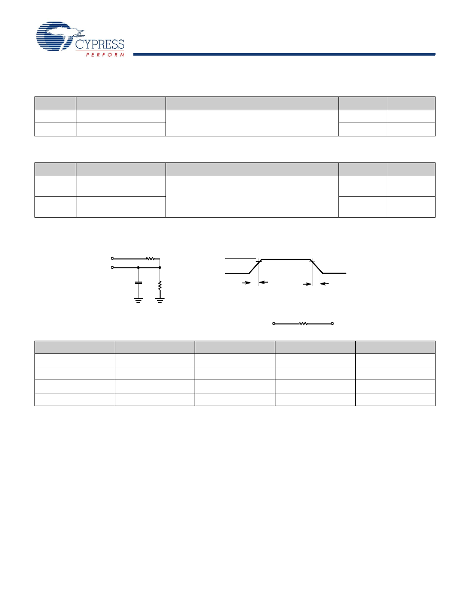
AC Test Loads and Waveforms
Parameters
2.5V
3.0V
5.0V
Unit
R1
16667
1103
1800
Ω
R2
15385
1554
990
Ω
R
TH
8000
645
639
Ω
V
TH
1.20
1.75
1.77
V
V
CC
V
CC
OUTPUT
R2
30 pF
INCLUDING
JIG AND
SCOPE
GND
90%
10%
90%
10%
Rise Time = 1 V/ns
Fall Time = 1 V/ns
OUTPUT
V
Equivalent to:
THÉ VENIN EQUIVALENT
ALL INPUT PULSES
R
TH
R1
TH
- CY7C1410AV18 (29 pages)
- CY7C1411JV18 (28 pages)
- CY7C1383FV25 (28 pages)
- CY14B256L (18 pages)
- CY7C1307BV25 (21 pages)
- CY7C1041DV33 (13 pages)
- CY62167EV18 (13 pages)
- Perform CY7C1565V18 (28 pages)
- STK11C68-5 (15 pages)
- 7C185-20 (11 pages)
- CY7C1168V18 (27 pages)
- CY7C1318CV18-250BZC (26 pages)
- CY7C1364C (18 pages)
- Perform CY7C1382D (34 pages)
- CY7C106D (11 pages)
- CY14E102N (21 pages)
- CY7C1418AV18 (31 pages)
- enCoRe CY7C638xx (83 pages)
- CY7C1018DV33 (9 pages)
- CY7C1292DV18 (23 pages)
- CY7C130 (19 pages)
- CY7C1424BV18 (30 pages)
- CY62157EV18 (12 pages)
- CY7C1392BV18 (31 pages)
- CY7C1302DV25 (18 pages)
- Perform CY7C1511KV18 (31 pages)
- West Bridge Astoria AN46860 (4 pages)
- CY7C1386FV25 (30 pages)
- CY7C1163V18 (29 pages)
- CY7C1266V18 (27 pages)
- CY7C1334H (13 pages)
- CY7C1018CV33 (7 pages)
- CY62136VN (12 pages)
- AN20639 (3 pages)
- CY7C1338G (17 pages)
- CY7C1462AV33 (27 pages)
- CY7C1145V18 (28 pages)
- STK11C88 (15 pages)
- CY7C1231H (12 pages)
- Perform CY7C142 (15 pages)
- CY14E256L (18 pages)
- STK15C88 (15 pages)
- CY7C1297H (15 pages)
- CY7C1441AV33 (31 pages)
- CapSense CY8C20x36 (34 pages)