Mm-f, Fig. 8 — motormaster – Carrier MOTORMASTER 48/50P5030-100 User Manual
Page 8
8
MMF-A MMF-B
FR-A FR-B
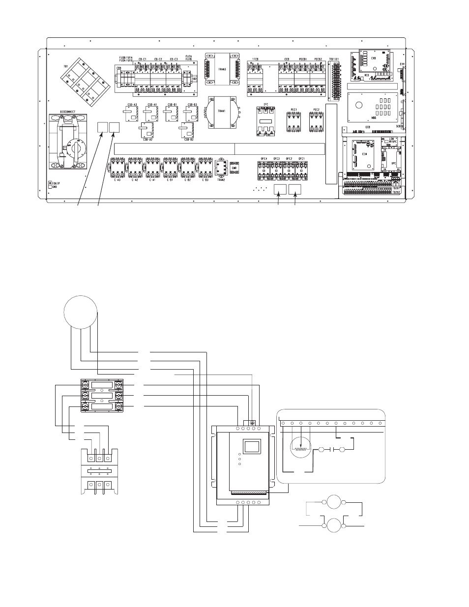
Fig. 7 — 48/50P Control Box Details
LEGEND
FR
— Fan Relay
MMF
— Motormaster V Fuse Block
a48-8565
OFM-1 (030,035,050-060)
OFM-3 (040)
MMV-A
L1
L2
L3
T1 T2 T3 B- B+
BLK
BLK
BLU
YEL
1
2
5
6
11
12
2
14
13A 13B 13C 15
5
9
MMPT
230-3-60 SHOWN.
REFER TO TABLE 4 FOR
ALTERNATE VOLTAGE
CONNECTIONS
FR-A
OFC1
13
14
C1
C2
ADD FAN RELAY (FR)
IN PARALLEL WITH OFC1
CCB
MM-F
BLU
YEL
A
B
C
TB
BLU
RED
BLK
GRN/YEL, DRAIN
RED
BLK
BLU
RED
BLK
GRY
WHT
11 12 13
22 23
21
FR-A
Fig. 8 — Motormaster
®
V Accessory Wiring — 48/50P030-060 Units
LEGEND
CCB
— Control Circuit Breaker
FR
— Fan Relay
MM-F
— Motormaster V Fuse Block
MMPT
— Motormaster Pressure Transducer
MMV
— Motormaster V Control
OFC
— Outdoor-Fan Contactor
OFM
— Outdoor-Fan Motor
TB
— Terminal Block
NOTE: Wire colors for MMPT:
2 — BLACK (A)
5 — GREEN (C)
6 — RED (B)
a48-8566