Fig. 3 — fan control – Carrier MOTORMASTER 48/50P5030-100 User Manual
Page 6
6
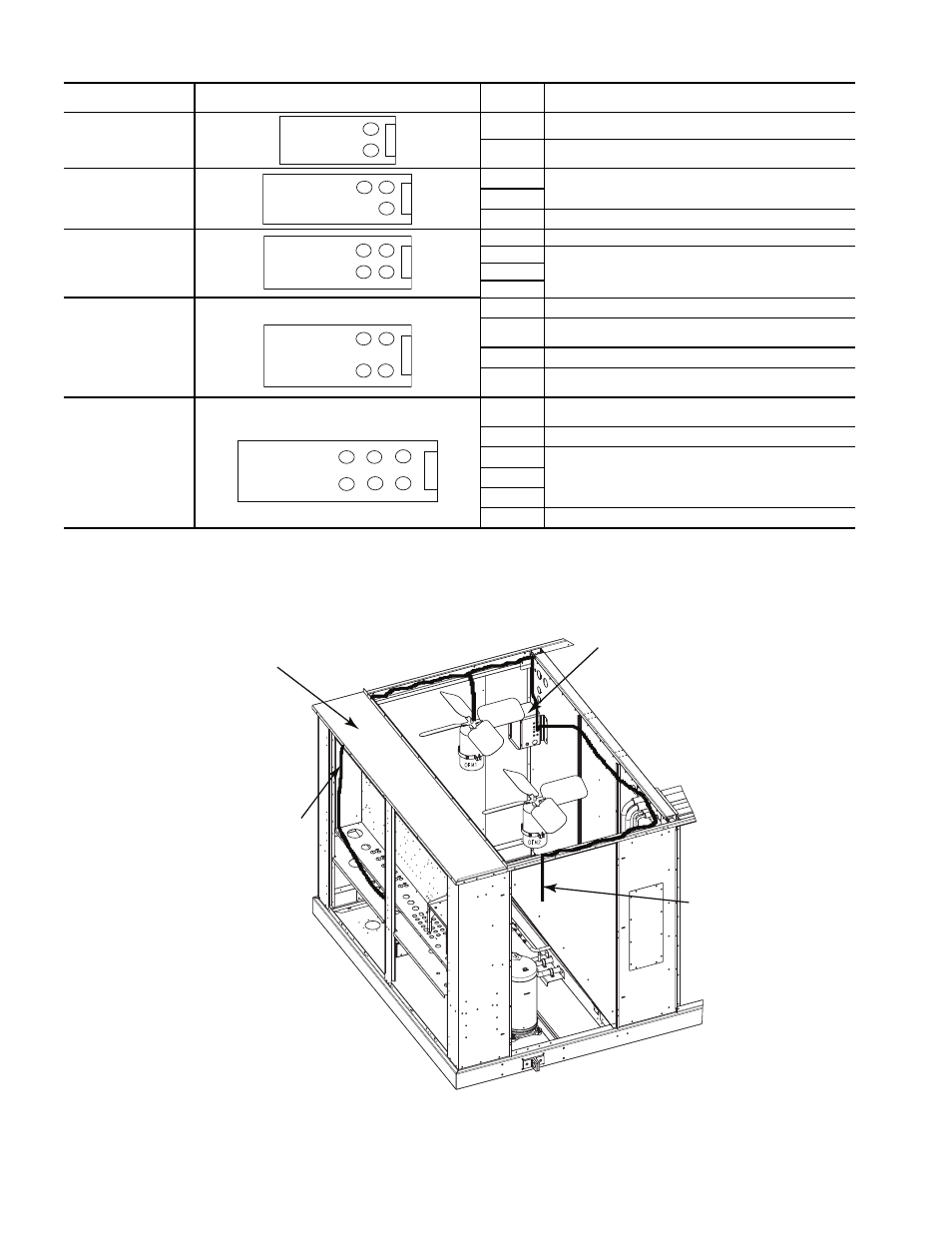
UNIT
48/50P
FAN ARRANGEMENT
FAN NO.
NORMAL CONTROL
030,035
1
MMV-A
2
Controlled by the ComfortLink™ head pressure
control routine
040
1
Controlled by the ComfortLink head pressure
control routine
2
3
MMV-A
050-060
1
MMV-A
2
Controlled by the ComfortLink head pressure
control routine
3
4
070,075
1
MMV-B
2
Controlled by the ComfortLink head pressure
control routine
3
MMV-A
4
Controlled by the ComfortLink head pressure
control routine
090,100
1
Controlled by the ComfortLink head pressure
control routine
2
MMV-B
3
Controlled by the ComfortLink head pressure
control routine
4
5
6
MMV-A
C
ont
rol Box
1
2
C
ont
rol Box
1
2
3
C
ont
rol Box
1
2
4
3
C
ont
rol Box
1
2
4
3
C
ont
rol Box
1
2
4
6
5
3
Fig. 3 — Fan Control
REMOVE PANEL
RUN ELECTRICAL HARNESSES UP THE SIDE
OF THE UNIT IN THE SPACE BETWEEN THE
CORNER POST AND THE CONTROL BOX.
ROUTE THE WIRING INTO THE WIRE TRAY,
THEN RUN APPROPRIATE WIRES TO OFM 1
AND MOTORMASTER CONTROL
MOTORMASTER
CONTROL
TRANSDUCER
HARNESS FROM
CIRCUIT A LIQUID LINE
TRANSDUCER TO MMV
Fig. 4 — MMV Control Mounting — 48/50P030,035 Units
a48-8562