Fig. 1 — motormaster® v control – Carrier MOTORMASTER 48/50P5030-100 User Manual
Page 2
2
Table 2 — Motormaster® V Control Package Contents — 48/50P030-060 Units
ITEM
CRLOWAMB033A00
CRLOWAMB034A00
CRLOWAMB035A00
Connector (
1
/
2
-in.)
HW60EA001
Connector (1-in.)
HW60HH006
Controller, 230 V 2 Hp
HR46TN001
—
—
Controller, 460 V 2 Hp
—
HR46TN002
—
Controller, 575 V 2 Hp
—
—
HR46TN003
Enclosure
30RA500381
Enclosure Cover
30RA500519
Enclosure Mounting Bracket
50EJ500656
Fan Relay
HN61KK055
Relay Base
HN79KK035
Fuse Block
HY11UT035
Fuse 15A, KTK-R, Class CC
—
HY10KB151 (3)
HY10KB151 (3)
Fuse 20A, KTK-R, Class CC
HY10KB200 (3)
—
—
Harness Assembly
48ZZ401971
Harness Assembly
48EJ402454
Harness Assembly
48ZZ402001
Label
48ZZ502002
Transducer
HK05ZZ001
Transducer Harness
48EJ403240
Varnish Cloth (Large)
48DA510141
Varnish Cloth (Small)
38C24601
Wire Tie
HY76TB123 (12)
Wire Tie
HY76TB045 (5)
Wire, 16 Gage 72 in. Long
WHT (1), GRY (1)
256
2
12 13A
13B
13C
1
2
3
TO MOTOR(S)
BLK
YEL
BLU
FROM FUSE BLOCK
B
TO PRESSURE
TRANSDUCER
1
2
5
6
1
12
2
14
13A
13B
13C
15
25
2
30
31
TXA
TXB
COM
+5V
TERMINAL
BLOCK
L1
L2
L3
T1 T2 T3 B- B+
PRESSURE
TRANSDUCER
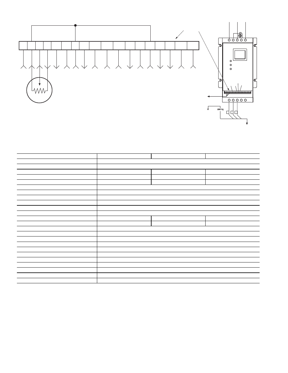
Fig. 1 — Motormaster® V Control
NOTE: Wire colors for MMPT:
2 — BLACK (A)
5 — GREEN (C)
6 — RED (B)