OSRAM SYLVANIA LEDstixx User Manual
Page 6
6
1.5.5
Install the new Optotronic OT75 power supply and re-use the previous ballast’s screws to secure the OT75 into the existing
mounting holes. (Fig. 11)
Fig. 11
Note:
1.
Depending on the size of the ballast removed, it may become necessary to drill an additional mounting
hole to match the foot print of the OT75.
2.
The AC ground wire from the line side wiring must be firmly bonded to the case of the OT75.
1.5.6
DC load side wiring from the power supply should never run in parallel to AC wiring. If AC line side wiring feeds from the top of
the cooler, the LEDstixx module should be mounted such that the power supply’s DC output wiring will feed the LEDstixx
module at the bottom of the cooler. Conversely, should AC line side wiring feed from the cooler’s bottom channel, then the
power supply’s output wiring must feed from the top of the cooler. The orientation of the LEDstixx receiving power from the
power supply must be the same throughout the case. Please refer to Figure 14.
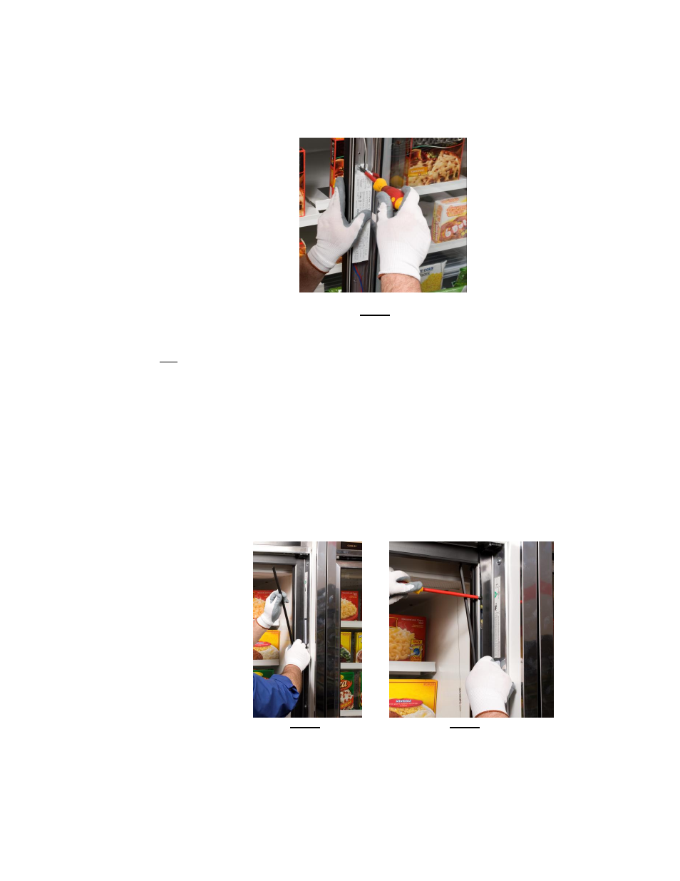
1.5.7
To identify the color coding of wiring feeding the tombstones in an adjacent mullion, access must be gained similarly to that
mentioned in 1.5.1. However, complete removal of the contact plate is not necessary. Partial “peel” back as shown in fig. 11 &
12 should be considered.
Fig. 12
Fig. 13