Exide Technologies Section 92.61 User Manual
Page 16
- 12 -
SECTION 9
9.0 Connections
9.1
Post Preparation
Using either a brass bristle suede shoe brush or 3M Scotch
Brite scouring pad, brighten the flat copper terminal surfaces
to ensure lowest resistance connections.
Apply a thin film of NO-OX-ID “A” grease (supplied with bat-
tery) to all terminal mating surfaces. This will preclude oxida-
tion after connections are completed.
9.2
Connections - System Terminals
Each system is supplied with a terminal plate assembly
for the positive and negative terminations. These should
always be used to provide proper connection to the operating
equipment and cell terminals. Any attempt to connect load
cables directly to cell terminals may compromise battery sys-
tem performance as well as the integrity of cell post seals.
For terminal plate assembly, see Figure 22 (6 cell modules
at low rate) or Figure 23. Consult layout/wiring diagram for
proper kit use. It is recommended that all components be
assembled in place with hardware torqued to 11.3 Newton-
meters (100 in-lbs). Retorque value is also 11.3 Newton-
meters (100 in-lbs).
Refer to Sections 9.1 and 9.3 for electrical contact surface
preparation of terminal plate components.
As shown, terminal plate assembly can be varied to satisfy
module terminal location as well as orientation of terminal
plate in a horizontal or vertical plane. Do not make connec-
tions to operating system at this time.
9.3
Connections - INTER-Module
Consult layout/wiring diagram for correct quantity of lead-
tin plated copper connectors required at each connection.
Follow procedure in Section 9.1 and brighten lead-tin plated
surfaces coming in contact with copper posts. Apply a film
of NO-OX-ID “A” grease to these areas. NOTE: Apply a
minimum amount of grease to cover the surface. As a rule:
“If you can see it, it’s too much”. Where multiple connectors
are required across any single connection, brighten both
sides of connectors along the entire length. Grease these
areas as well. It is recommended when installing connec-
tors that the upper bolts be installed first to reduced risk of
accidental shorting.
Cells are interconnected with connectors and hardware as
shown in Figures 21A and 21B
9.4
Connections - INTER-Stack
Multiple stacks end to end are interconnected as shown in
Figure 21C and 21D. Follow procedures in Section 9.1 and
Section 9.3. Also see Section 9.5, Connections - Torquing.
9.5
Connections - Torquing
When all inter-module connections have been installed, tight-
en all connections to 11.3 Newton-meters (100 in-lbs) Use
insulated tools. All connections should be rechecked after
the initial charge, due to heating during charge.
9.6
Connection - Check
Again, visually check to see that all module terminals are
connected positive (+) to negative (-) throughout the battery.
Also measure the total voltage from terminal plate to terminal
plate. This should be approximately equal to 2.15 volts times
the number of cells in the system, e.g., a 24 cell system
would read: 24 x 2.15v = 51.6 volts.
9.7
Connection Resistance
Electrical integrity of connections can be objectively estab-
lished by measuring the resistance of each connection.
These resistances are typically in the microhm range.
Meters are available which determine connection resistance
in microhms. Be sure that the probes are touching only the
posts to ensure that the contact resistance of connector to
post is included in the reading.
Resistance measurements or microhm measurements
should be taken at the time of installation and annually there-
after. Initial measurements at installation become the bench
mark values and should be recorded for future monitoring of
electrical integrity.
It is important that the bench mark value for all similar con-
nections be no greater than 10% over the average. If any
connection resistance exceeds the average by more than
10%, the connection should be remade so that an accept-
able bench mark value is established.
Bench mark values for connection resistances should also
be established for terminal plates, where used, as well as
cable connections. Bench mark values should preferably be
established upon installation.
All bench mark values should be recorded. Annually, all con-
nection resistances should be re-measured. Any connection
which has a resistance value 20% above its benchmark
value should be corrected.
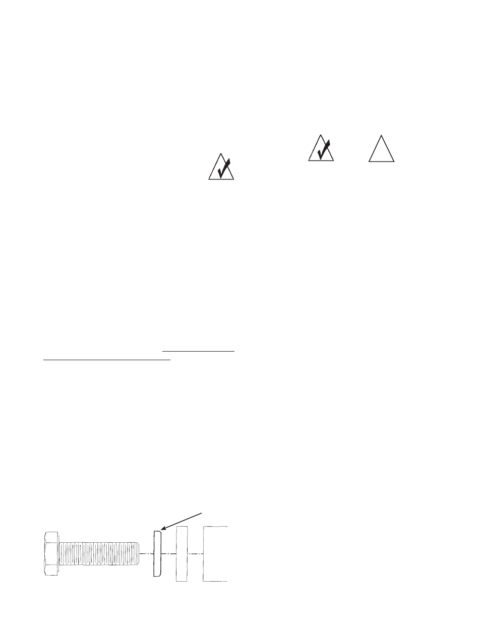
!
WASHERS SHOULD BE INSTALLED WITH THE CURVED
EDGE TOWARD THE CONNECTORS.
BOLT
WASHER CONNECTOR
POST