Exide Technologies Section 92.61 User Manual
Page 15
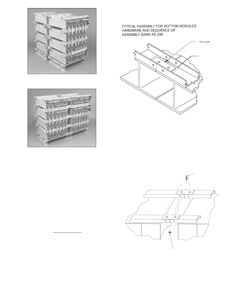
8.2.1 Stack Tie Plate
To achieve maximum stack stability, especially where seismic
conditions may exist, as well as proper interfacing of inter-
stack connections, metal tie plates are provided. The plates
used on stacks end to end are 3” x 1” x 1/8” with two 9/16”
holes. Use one tie plate at each interface on only the base
and top modules of adjacent stacks. See Figures 20A and
20B.
Position plates on the front and back channels and secure
with hardware shown. Where stacks have different levels,
install plates on shorter stack top module and adjacent mod-
ule. Torque hardware to 47 Newton-meters (35 Ft-Lbs).
This completes the mechanical assembly of the battery system.
For installation of connections and terminal plate assembly,
see Section 9.
For installation of protective module cover, see Section 10.
- 11 -
TIE PLATE TOP MODULES
Figure 20B
HORIZONTAL STACKS — BACK TO BACK POSITIONING
Figure 19A
COMPLETED HORIZONTAL STACKS — SIDE BY SIDE
Figure 19B
TIE PLATE BOTTOM MODULES
Figure 20A
SEISMIC SHIM
INSTALLED UNDER
TIE PLATE WHERE
APPLICABLE
M10 SERRATED
FLANGE BOLT
M10 SERRATED
FLANGE NUT