Parts diagram – CCI Thermal Technologies CR1 - Trito Corrosion-Resistant Washdown Unit Heater User Manual
Page 6
10
7
3
12
15
14
13
8
5
4
11
9
2
WALL MOUNT
BRACKET DETAIL
217.0
126
126.0
152
2
2
1
19
6
22
21
17
20
26
20
23
25
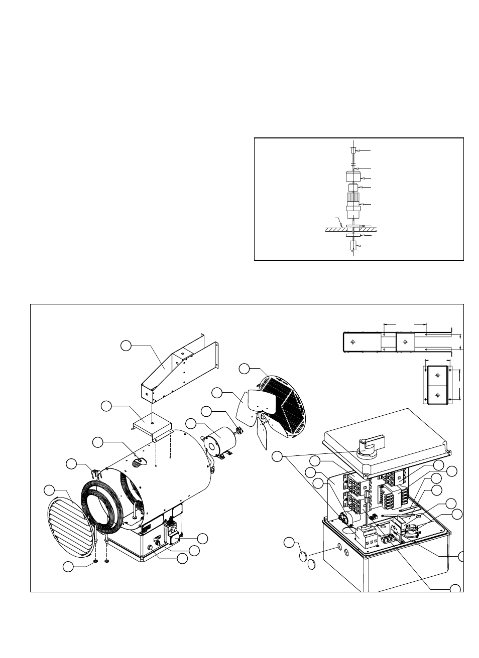
PARTS DIAGRAM
TEMPERATURE HIGH-LIMIT
1. Remove discharge grill from heater. Remove clips
securing bulb and capillary to cabinet.
2. Inside electrical enclosure, remove lock nut from
high-limit compression fitting and remove fitting from
enclosure.
3. Remove compression nut from the fitting (see Figure
11). Remove seal from fitting. Remove fitting from
capillary.
4. Remove high-limit switch from the enclosure.
5. Replace high-limit with factory-supplied replacement
high-limit.
6. Reinstall high-limit switch to bracket in the control
enclosure.
7. Slip capillary sleeve over capillary.
Note: For 25 to 39 kW heaters, the sleeve must be cut
to 8.25 in. (210 mm). For 15 and 20 kW heaters, the
sleeve must be cut to 14.125 in. (360 mm). For 3 to
10 kW heaters, sleeve does not have to be cut to
length.
8. Slide lock nut over bulb and capillary. Insert bulb and
capillary through the enclosure opening.
9. Place compression fitting body over capillary. Install
seal on capillary and insert seal into body of fitting
(see Figure 11).
10. Loosely install top nut onto compression seal body.
Secure fitting to enclosure with lock nut on the inside
of the enclosure. Tighten lock nut to ensure watertight
seal.
11. Reinstall the bulb and capillary using the original
clips. Ensure the bulb is in the same position as the
previous high-limit. The bulb tip should be 3.94 in.
(100 mm) from the discharge edge of the cabinet.
12. Tighten top nut on compression seal.
BULB
CAPILLARY
NUT
SEAL
COMPRESSION
FITTING BODY
O-RING
CABINET
LOCKNUT
SLEEVE
– 6 –
Figure 11
Figure 12